🗊 Презентация The Verilog Language

Нажмите для полного просмотра!
The Verilog Language, слайд №1 The Verilog Language, слайд №2 The Verilog Language, слайд №3 The Verilog Language, слайд №4 The Verilog Language, слайд №5 The Verilog Language, слайд №6 The Verilog Language, слайд №7 The Verilog Language, слайд №8 The Verilog Language, слайд №9 The Verilog Language, слайд №10 The Verilog Language, слайд №11 The Verilog Language, слайд №12 The Verilog Language, слайд №13 The Verilog Language, слайд №14 The Verilog Language, слайд №15 The Verilog Language, слайд №16 The Verilog Language, слайд №17 The Verilog Language, слайд №18 The Verilog Language, слайд №19 The Verilog Language, слайд №20 The Verilog Language, слайд №21 The Verilog Language, слайд №22 The Verilog Language, слайд №23 The Verilog Language, слайд №24 The Verilog Language, слайд №25 The Verilog Language, слайд №26 The Verilog Language, слайд №27 The Verilog Language, слайд №28 The Verilog Language, слайд №29 The Verilog Language, слайд №30 The Verilog Language, слайд №31 The Verilog Language, слайд №32 The Verilog Language, слайд №33 The Verilog Language, слайд №34 The Verilog Language, слайд №35 The Verilog Language, слайд №36 The Verilog Language, слайд №37 The Verilog Language, слайд №38 The Verilog Language, слайд №39 The Verilog Language, слайд №40 The Verilog Language, слайд №41 The Verilog Language, слайд №42 The Verilog Language, слайд №43 The Verilog Language, слайд №44 The Verilog Language, слайд №45 The Verilog Language, слайд №46 The Verilog Language, слайд №47 The Verilog Language, слайд №48 The Verilog Language, слайд №49 The Verilog Language, слайд №50 The Verilog Language, слайд №51 The Verilog Language, слайд №52 The Verilog Language, слайд №53 The Verilog Language, слайд №54 The Verilog Language, слайд №55 The Verilog Language, слайд №56 The Verilog Language, слайд №57 The Verilog Language, слайд №58 The Verilog Language, слайд №59 The Verilog Language, слайд №60 The Verilog Language, слайд №61

Содержание
Вы можете ознакомиться и скачать презентацию на тему The Verilog Language. Доклад-сообщение содержит 61 слайдов. Презентации для любого класса можно скачать бесплатно. Если материал и наш сайт презентаций Mypresentation Вам понравились – поделитесь им с друзьями с помощью социальных кнопок и добавьте в закладки в своем браузере.
Слайды и текст этой презентации


Слайд 1


The Verilog Language These slides were developed by Prof. Stephen A. Edwards CS dept., Columbia University
Описание слайда:
The Verilog Language These slides were developed by Prof. Stephen A. Edwards CS dept., Columbia University

Слайд 2


The Verilog Language Originally a modeling language for a very efficient event-driven digital logic simulator Later pushed into use as a...
Описание слайда:
The Verilog Language Originally a modeling language for a very efficient event-driven digital logic simulator Later pushed into use as a specification language for logic synthesis Now, one of the two most commonly-used languages in digital hardware design (VHDL is the other) Virtually every chip (FPGA, ASIC, etc.) is designed in part using one of these two languages Combines structural and behavioral modeling styles

Слайд 3


Structural Modeling When Verilog was first developed (1984) most logic simulators operated on netlists Netlist: list of gates and how they’re...
Описание слайда:
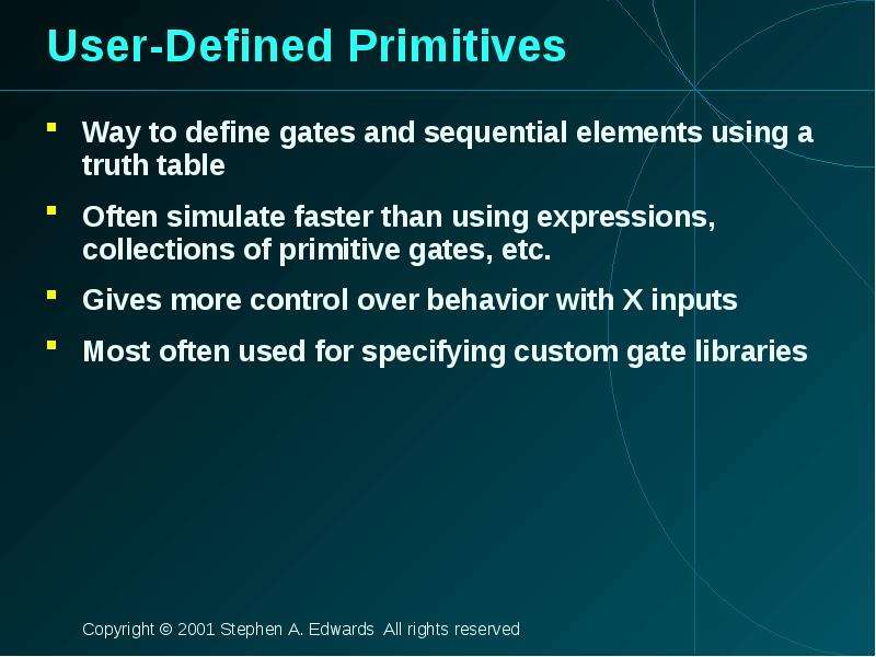
Structural Modeling When Verilog was first developed (1984) most logic simulators operated on netlists Netlist: list of gates and how they’re connected A natural representation of a digital logic circuit Not the most convenient way to express test benches

Слайд 4


Behavioral Modeling A much easier way to write testbenches Also good for more abstract models of circuits Easier to write Simulates faster More...
Описание слайда:
Behavioral Modeling A much easier way to write testbenches Also good for more abstract models of circuits Easier to write Simulates faster More flexible Provides sequencing Verilog succeeded in part because it allowed both the model and the testbench to be described together

Слайд 5


How Verilog Is Used Virtually every ASIC is designed using either Verilog or VHDL (a similar language) Behavioral modeling with some structural...
Описание слайда:
How Verilog Is Used Virtually every ASIC is designed using either Verilog or VHDL (a similar language) Behavioral modeling with some structural elements “Synthesis subset” Can be translated using Synopsys’ Design Compiler or others into a netlist Design written in Verilog Simulated to death to check functionality Synthesized (netlist generated) Static timing analysis to check timing

Слайд 6


Two Main Components of Verilog Concurrent, event-triggered processes (behavioral) Initial and Always blocks Imperative code that can perform standard...
Описание слайда:
Two Main Components of Verilog Concurrent, event-triggered processes (behavioral) Initial and Always blocks Imperative code that can perform standard data manipulation tasks (assignment, if-then, case) Processes run until they delay for a period of time or wait for a triggering event Structure (Plumbing) Verilog program build from modules with I/O interfaces Modules may contain instances of other modules Modules contain local signals, etc. Module configuration is static and all run concurrently

Слайд 7


Two Main Data Types Nets represent connections between things Do not hold their value Take their value from a driver such as a gate or other module...
Описание слайда:
Two Main Data Types Nets represent connections between things Do not hold their value Take their value from a driver such as a gate or other module Cannot be assigned in an initial or always block Regs represent data storage Behave exactly like memory in a computer Hold their value until explicitly assigned in an initial or always block Never connected to something Can be used to model latches, flip-flops, etc., but do not correspond exactly Shared variables with all their attendant problems

Слайд 8


Discrete-event Simulation Basic idea: only do work when something changes Centered around an event queue Contains events labeled with the simulated...
Описание слайда:
Discrete-event Simulation Basic idea: only do work when something changes Centered around an event queue Contains events labeled with the simulated time at which they are to be executed Basic simulation paradigm Execute every event for the current simulated time Doing this changes system state and may schedule events in the future When there are no events left at the current time instance, advance simulated time soonest event in the queue

Слайд 9


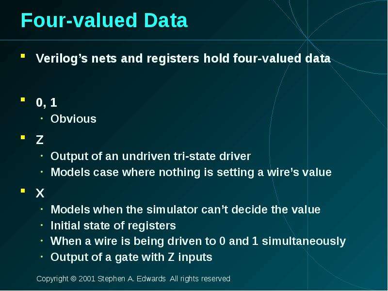
Four-valued Data Verilog’s nets and registers hold four-valued data 0, 1 Obvious Z Output of an undriven tri-state driver Models case where nothing...
Описание слайда:
Four-valued Data Verilog’s nets and registers hold four-valued data 0, 1 Obvious Z Output of an undriven tri-state driver Models case where nothing is setting a wire’s value X Models when the simulator can’t decide the value Initial state of registers When a wire is being driven to 0 and 1 simultaneously Output of a gate with Z inputs

Слайд 10


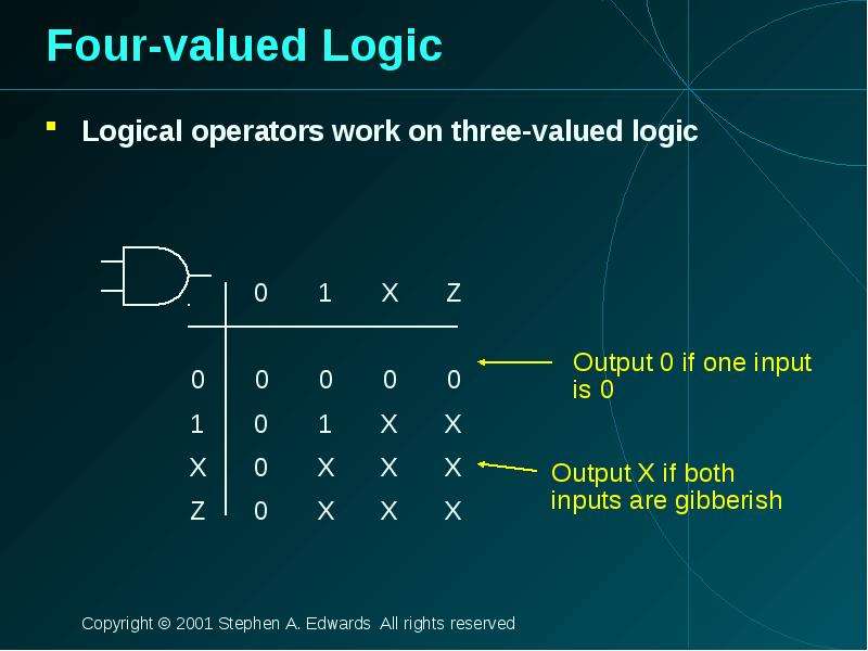
Four-valued Logic Logical operators work on three-valued logic
Описание слайда:
Four-valued Logic Logical operators work on three-valued logic

Слайд 11


Structural Modeling
Описание слайда:
Structural Modeling

Слайд 12


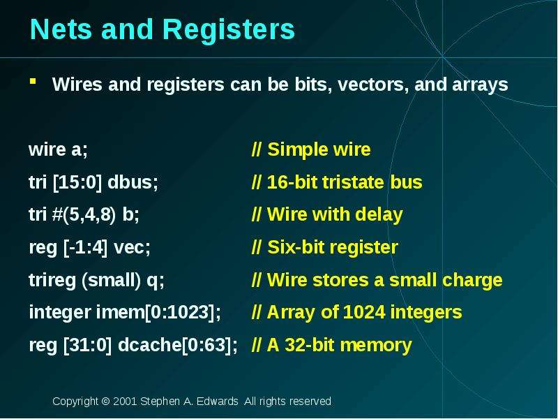
Nets and Registers Wires and registers can be bits, vectors, and arrays wire a; // Simple wire tri [15:0] dbus; // 16-bit tristate bus tri #(5,4,8)...
Описание слайда:
Nets and Registers Wires and registers can be bits, vectors, and arrays wire a; // Simple wire tri [15:0] dbus; // 16-bit tristate bus tri #(5,4,8) b; // Wire with delay reg [-1:4] vec; // Six-bit register trireg (small) q; // Wire stores a small charge integer imem[0:1023]; // Array of 1024 integers reg [31:0] dcache[0:63]; // A 32-bit memory

Слайд 13


Modules and Instances Basic structure of a Verilog module: module mymod(output1, output2, … input1, input2); output output1; output [3:0] output2;...
Описание слайда:
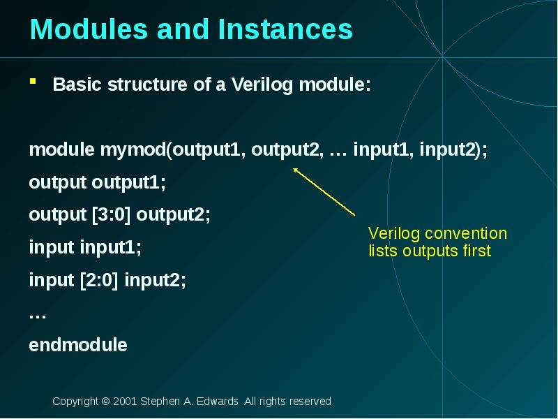
Modules and Instances Basic structure of a Verilog module: module mymod(output1, output2, … input1, input2); output output1; output [3:0] output2; input input1; input [2:0] input2; … endmodule

Слайд 14


Instantiating a Module Instances of module mymod(y, a, b); look like mymod mm1(y1, a1, b1); // Connect-by-position mymod (y2, a1, b1), (y3, a2, b2);...
Описание слайда:
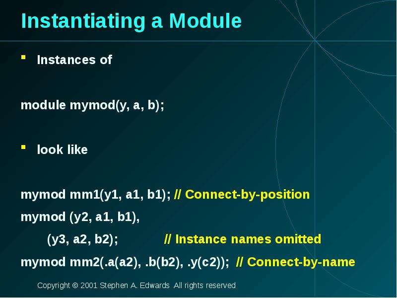
Instantiating a Module Instances of module mymod(y, a, b); look like mymod mm1(y1, a1, b1); // Connect-by-position mymod (y2, a1, b1), (y3, a2, b2); // Instance names omitted mymod mm2(.a(a2), .b(b2), .y(c2)); // Connect-by-name

Слайд 15


Gate-level Primitives Verilog provides the following: and nand logical AND/NAND or nor logical OR/NOR xor xnor logical XOR/XNOR buf not...
Описание слайда:
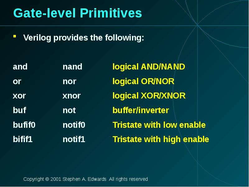
Gate-level Primitives Verilog provides the following: and nand logical AND/NAND or nor logical OR/NOR xor xnor logical XOR/XNOR buf not buffer/inverter bufif0 notif0 Tristate with low enable bifif1 notif1 Tristate with high enable

Слайд 16


Delays on Primitive Instances Instances of primitives may include delays buf b1(a, b); // Zero delay buf #3 b2(c, d); // Delay of 3 buf #(4,5) b3(e,...
Описание слайда:
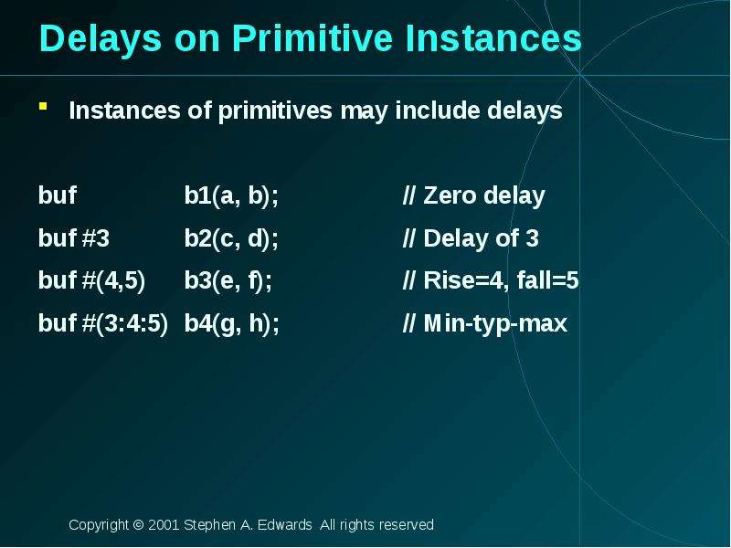
Delays on Primitive Instances Instances of primitives may include delays buf b1(a, b); // Zero delay buf #3 b2(c, d); // Delay of 3 buf #(4,5) b3(e, f); // Rise=4, fall=5 buf #(3:4:5) b4(g, h); // Min-typ-max

Слайд 17


User-Defined Primitives Way to define gates and sequential elements using a truth table Often simulate faster than using expressions, collections of...
Описание слайда:
User-Defined Primitives Way to define gates and sequential elements using a truth table Often simulate faster than using expressions, collections of primitive gates, etc. Gives more control over behavior with X inputs Most often used for specifying custom gate libraries

Слайд 18


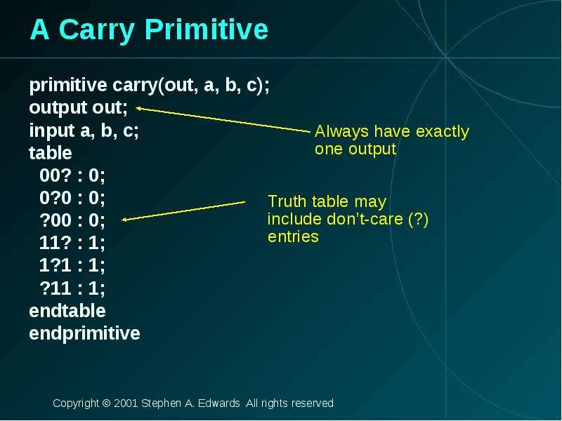
A Carry Primitive primitive carry(out, a, b, c); output out; input a, b, c; table 00? : 0; 0?0 : 0; ?00 : 0; 11? : 1; 1?1 : 1; ?11 : 1; endtable...
Описание слайда:
A Carry Primitive primitive carry(out, a, b, c); output out; input a, b, c; table 00? : 0; 0?0 : 0; ?00 : 0; 11? : 1; 1?1 : 1; ?11 : 1; endtable endprimitive

Слайд 19


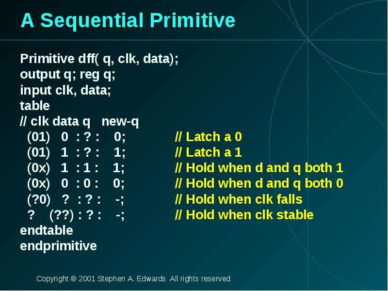
A Sequential Primitive Primitive dff( q, clk, data); output q; reg q; input clk, data; table // clk data q new-q (01) 0 : ? : 0; // Latch a 0 (01) 1...
Описание слайда:
A Sequential Primitive Primitive dff( q, clk, data); output q; reg q; input clk, data; table // clk data q new-q (01) 0 : ? : 0; // Latch a 0 (01) 1 : ? : 1; // Latch a 1 (0x) 1 : 1 : 1; // Hold when d and q both 1 (0x) 0 : 0 : 0; // Hold when d and q both 0 (?0) ? : ? : -; // Hold when clk falls ? (??) : ? : -; // Hold when clk stable endtable endprimitive

Слайд 20


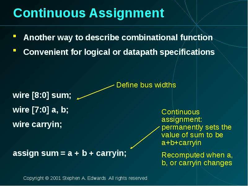
Continuous Assignment Another way to describe combinational function Convenient for logical or datapath specifications wire [8:0] sum; wire [7:0] a,...
Описание слайда:
Continuous Assignment Another way to describe combinational function Convenient for logical or datapath specifications wire [8:0] sum; wire [7:0] a, b; wire carryin; assign sum = a + b + carryin;

Слайд 21


Behavioral Modeling
Описание слайда:
Behavioral Modeling

Слайд 22


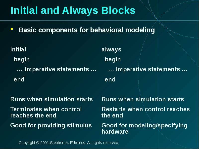
Initial and Always Blocks Basic components for behavioral modeling
Описание слайда:
Initial and Always Blocks Basic components for behavioral modeling

Слайд 23


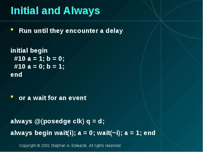
Initial and Always Run until they encounter a delay initial begin #10 a = 1; b = 0; #10 a = 0; b = 1; end or a wait for an event always @(posedge...
Описание слайда:
Initial and Always Run until they encounter a delay initial begin #10 a = 1; b = 0; #10 a = 0; b = 1; end or a wait for an event always @(posedge clk) q = d; always begin wait(i); a = 0; wait(~i); a = 1; end

Слайд 24


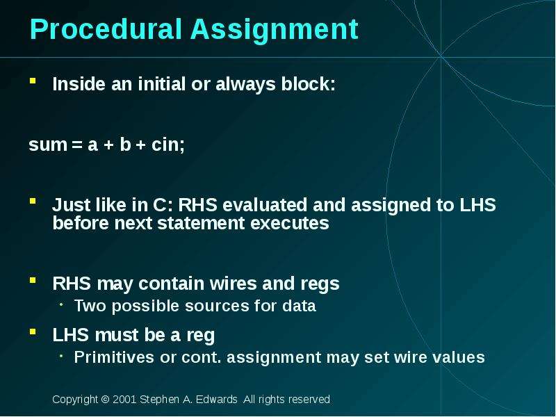
Procedural Assignment Inside an initial or always block: sum = a + b + cin; Just like in C: RHS evaluated and assigned to LHS before next statement...
Описание слайда:
Procedural Assignment Inside an initial or always block: sum = a + b + cin; Just like in C: RHS evaluated and assigned to LHS before next statement executes RHS may contain wires and regs Two possible sources for data LHS must be a reg Primitives or cont. assignment may set wire values

Слайд 25


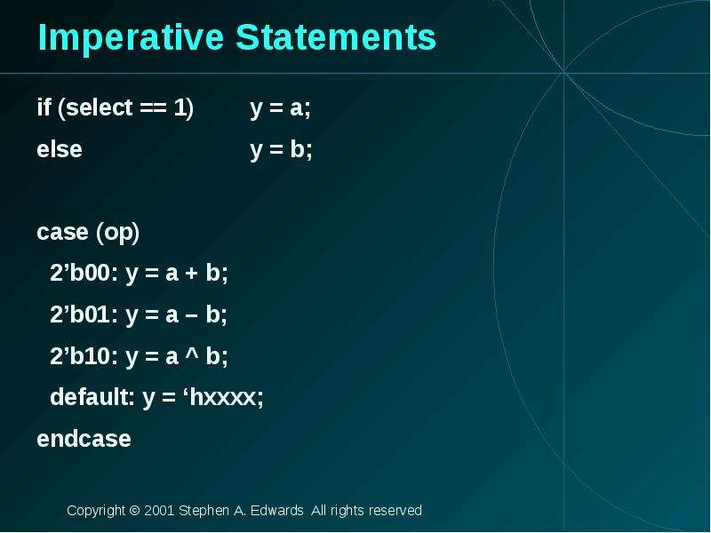
Imperative Statements if (select == 1) y = a; else y = b; case (op) 2’b00: y = a + b; 2’b01: y = a – b; 2’b10: y = a ^ b; default: y = ‘hxxxx; endcase
Описание слайда:
Imperative Statements if (select == 1) y = a; else y = b; case (op) 2’b00: y = a + b; 2’b01: y = a – b; 2’b10: y = a ^ b; default: y = ‘hxxxx; endcase

Слайд 26


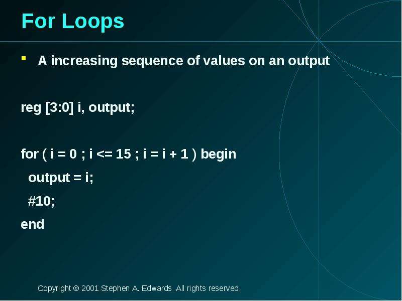
For Loops A increasing sequence of values on an output reg [3:0] i, output; for ( i = 0 ; i
Описание слайда:
For Loops A increasing sequence of values on an output reg [3:0] i, output; for ( i = 0 ; i

Слайд 27


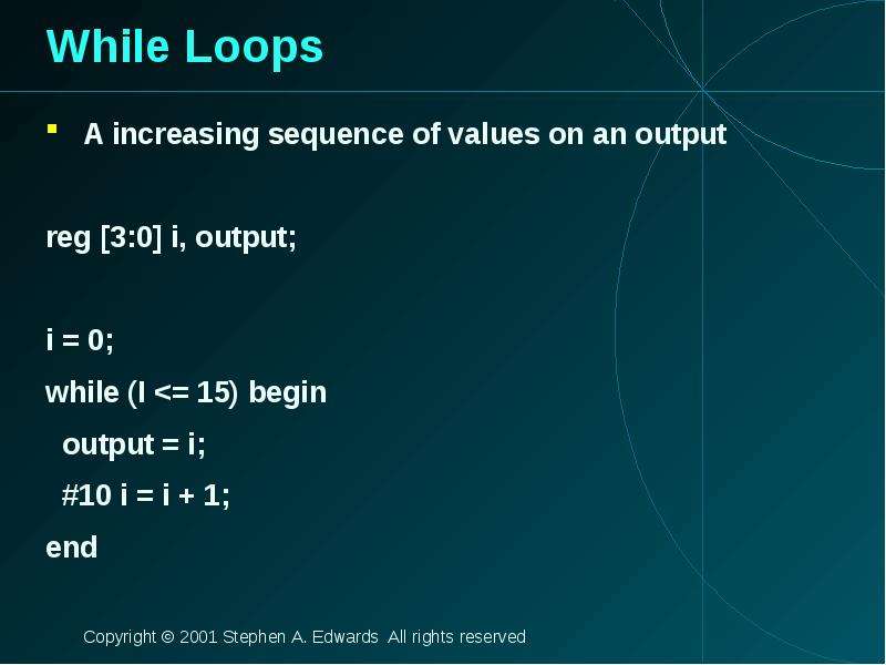
While Loops A increasing sequence of values on an output reg [3:0] i, output; i = 0; while (I
Описание слайда:
While Loops A increasing sequence of values on an output reg [3:0] i, output; i = 0; while (I

Слайд 28


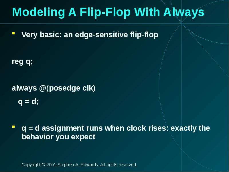
Modeling A Flip-Flop With Always Very basic: an edge-sensitive flip-flop reg q; always @(posedge clk) q = d; q = d assignment runs when clock rises:...
Описание слайда:
Modeling A Flip-Flop With Always Very basic: an edge-sensitive flip-flop reg q; always @(posedge clk) q = d; q = d assignment runs when clock rises: exactly the behavior you expect

Слайд 29


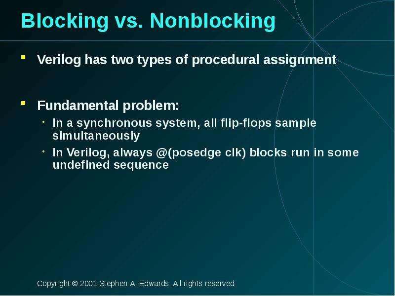
Blocking vs. Nonblocking Verilog has two types of procedural assignment Fundamental problem: In a synchronous system, all flip-flops sample...
Описание слайда:
Blocking vs. Nonblocking Verilog has two types of procedural assignment Fundamental problem: In a synchronous system, all flip-flops sample simultaneously In Verilog, always @(posedge clk) blocks run in some undefined sequence

Слайд 30


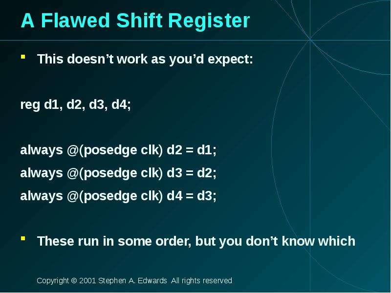
A Flawed Shift Register This doesn’t work as you’d expect: reg d1, d2, d3, d4; always @(posedge clk) d2 = d1; always @(posedge clk) d3 = d2; always...
Описание слайда:
A Flawed Shift Register This doesn’t work as you’d expect: reg d1, d2, d3, d4; always @(posedge clk) d2 = d1; always @(posedge clk) d3 = d2; always @(posedge clk) d4 = d3; These run in some order, but you don’t know which

Слайд 31


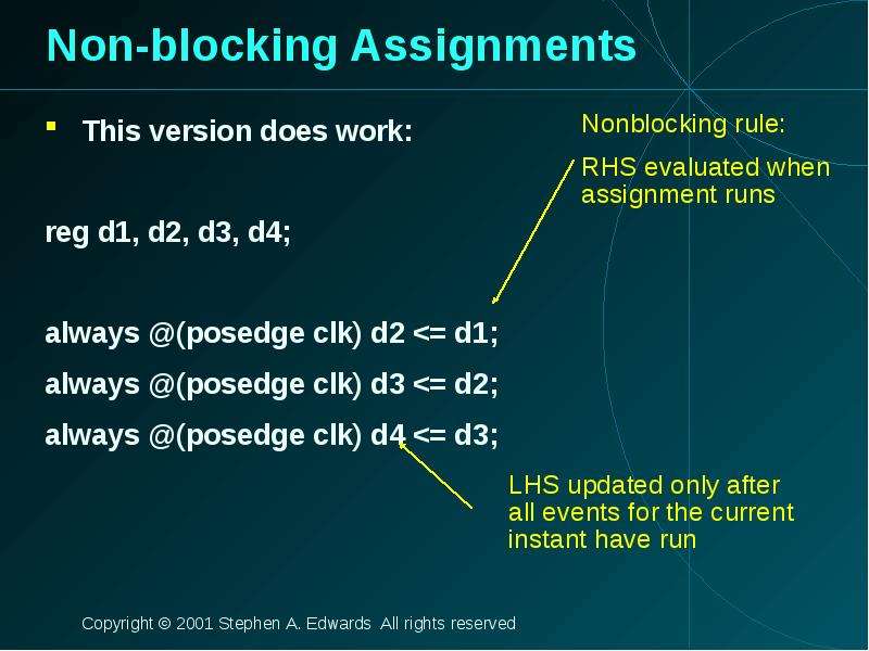
Non-blocking Assignments This version does work: reg d1, d2, d3, d4; always @(posedge clk) d2
Описание слайда:
Non-blocking Assignments This version does work: reg d1, d2, d3, d4; always @(posedge clk) d2

Слайд 32


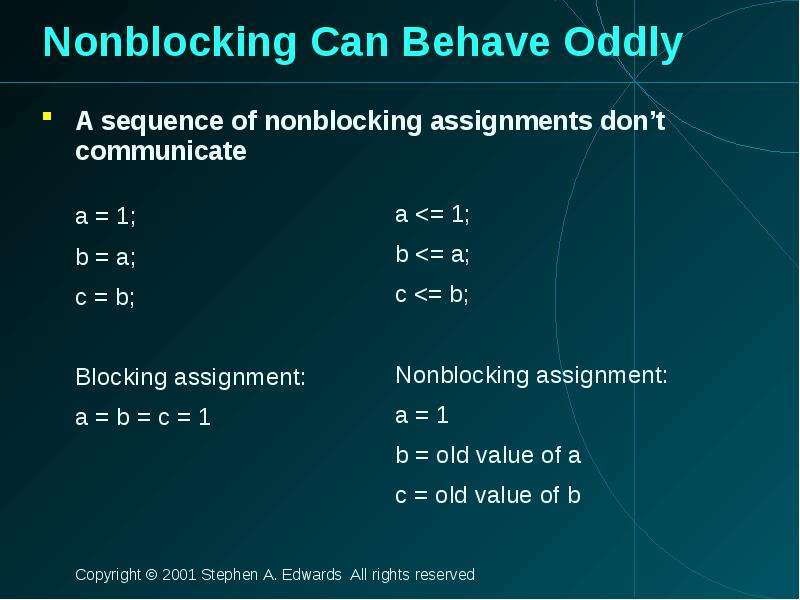
Nonblocking Can Behave Oddly A sequence of nonblocking assignments don’t communicate
Описание слайда:
Nonblocking Can Behave Oddly A sequence of nonblocking assignments don’t communicate

Слайд 33


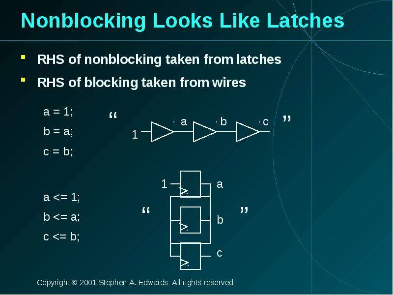
Nonblocking Looks Like Latches RHS of nonblocking taken from latches RHS of blocking taken from wires
Описание слайда:
Nonblocking Looks Like Latches RHS of nonblocking taken from latches RHS of blocking taken from wires

Слайд 34


Building Behavioral Models
Описание слайда:
Building Behavioral Models

Слайд 35


Modeling FSMs Behaviorally There are many ways to do it: Define the next-state logic combinationally and define the state-holding latches explicitly...
Описание слайда:
Modeling FSMs Behaviorally There are many ways to do it: Define the next-state logic combinationally and define the state-holding latches explicitly Define the behavior in a single always @(posedge clk) block Variations on these themes

Слайд 36


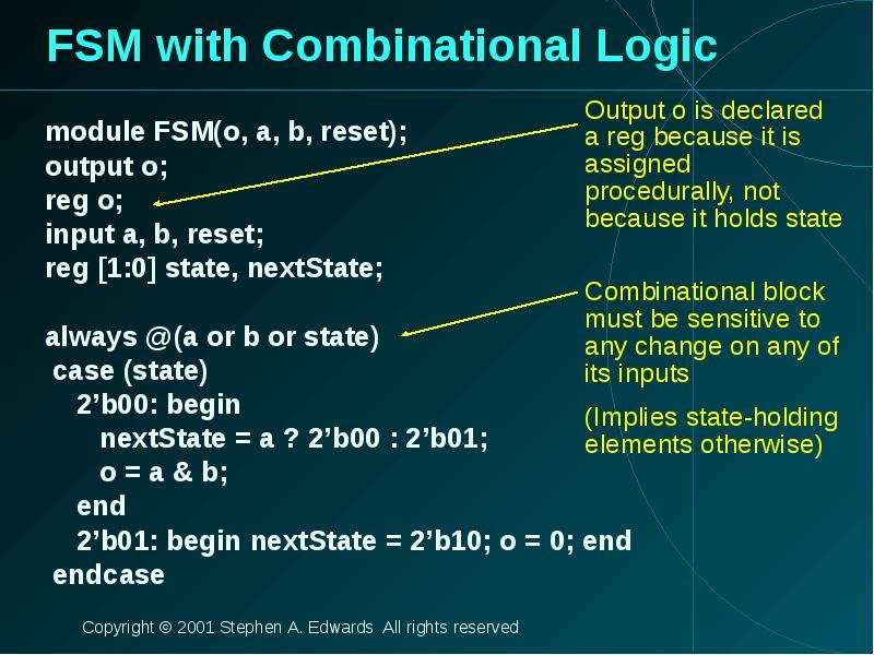
FSM with Combinational Logic module FSM(o, a, b, reset); output o; reg o; input a, b, reset; reg [1:0] state, nextState; always @(a or b or state)...
Описание слайда:
FSM with Combinational Logic module FSM(o, a, b, reset); output o; reg o; input a, b, reset; reg [1:0] state, nextState; always @(a or b or state) case (state) 2’b00: begin nextState = a ? 2’b00 : 2’b01; o = a & b; end 2’b01: begin nextState = 2’b10; o = 0; end endcase

Слайд 37


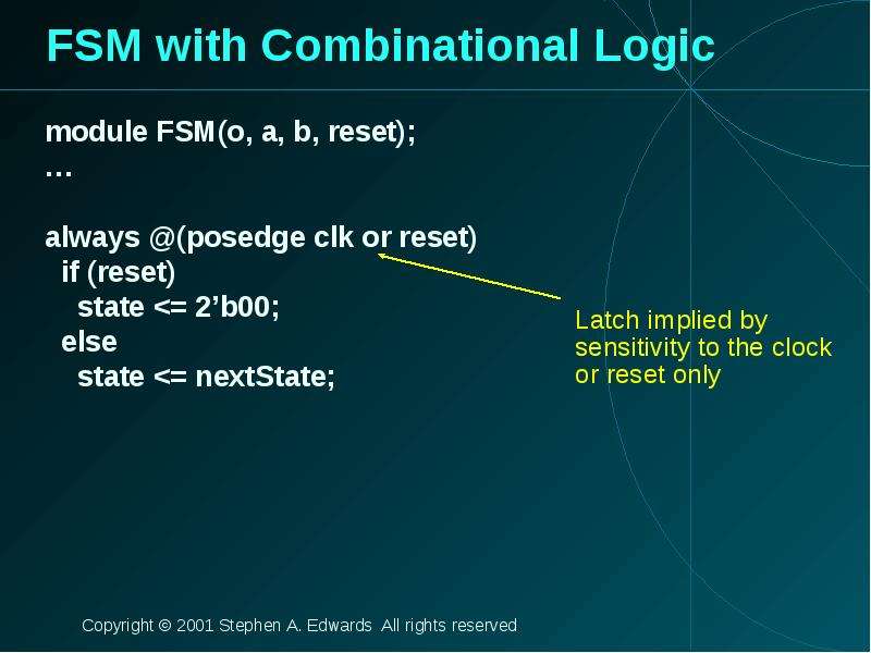
FSM with Combinational Logic module FSM(o, a, b, reset); … always @(posedge clk or reset) if (reset) state
Описание слайда:
FSM with Combinational Logic module FSM(o, a, b, reset); … always @(posedge clk or reset) if (reset) state

Слайд 38


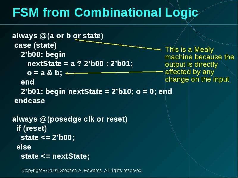
FSM from Combinational Logic always @(a or b or state) case (state) 2’b00: begin nextState = a ? 2’b00 : 2’b01; o = a & b; end 2’b01: begin nextState...
Описание слайда:
FSM from Combinational Logic always @(a or b or state) case (state) 2’b00: begin nextState = a ? 2’b00 : 2’b01; o = a & b; end 2’b01: begin nextState = 2’b10; o = 0; end endcase always @(posedge clk or reset) if (reset) state

Слайд 39


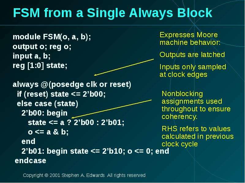
FSM from a Single Always Block module FSM(o, a, b); output o; reg o; input a, b; reg [1:0] state; always @(posedge clk or reset) if (reset) state
Описание слайда:
FSM from a Single Always Block module FSM(o, a, b); output o; reg o; input a, b; reg [1:0] state; always @(posedge clk or reset) if (reset) state

Слайд 40


Simulating Verilog
Описание слайда:
Simulating Verilog

Слайд 41


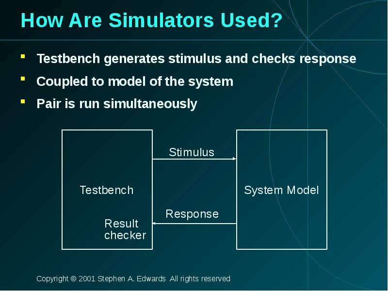
How Are Simulators Used? Testbench generates stimulus and checks response Coupled to model of the system Pair is run simultaneously
Описание слайда:
How Are Simulators Used? Testbench generates stimulus and checks response Coupled to model of the system Pair is run simultaneously

Слайд 42


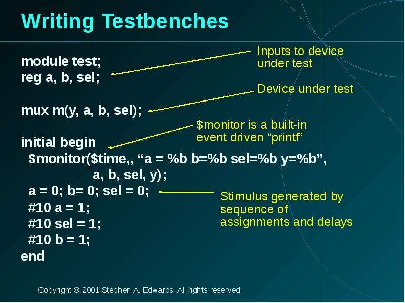
Writing Testbenches module test; reg a, b, sel; mux m(y, a, b, sel); initial begin $monitor($time,, “a = %b b=%b sel=%b y=%b”, a, b, sel, y); a = 0;...
Описание слайда:
Writing Testbenches module test; reg a, b, sel; mux m(y, a, b, sel); initial begin $monitor($time,, “a = %b b=%b sel=%b y=%b”, a, b, sel, y); a = 0; b= 0; sel = 0; #10 a = 1; #10 sel = 1; #10 b = 1; end

Слайд 43


Simulation Behavior Scheduled using an event queue Non-preemptive, no priorities A process must explicitly request a context switch Events at a...
Описание слайда:
Simulation Behavior Scheduled using an event queue Non-preemptive, no priorities A process must explicitly request a context switch Events at a particular time unordered Scheduler runs each event at the current time, possibly scheduling more as a result

Слайд 44


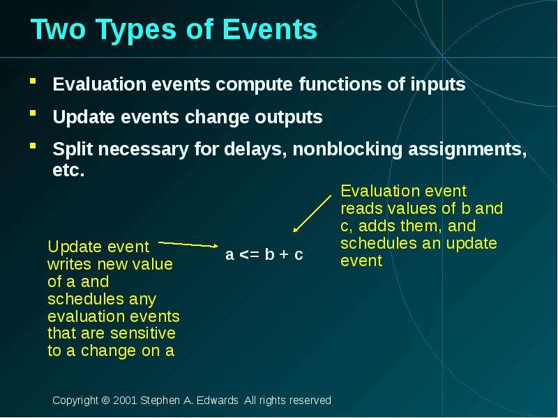
Two Types of Events Evaluation events compute functions of inputs Update events change outputs Split necessary for delays, nonblocking assignments,...
Описание слайда:
Two Types of Events Evaluation events compute functions of inputs Update events change outputs Split necessary for delays, nonblocking assignments, etc.

Слайд 45


Simulation Behavior Concurrent processes (initial, always) run until they stop at one of the following #42 Schedule process to resume 42 time units...
Описание слайда:
Simulation Behavior Concurrent processes (initial, always) run until they stop at one of the following #42 Schedule process to resume 42 time units from now wait(cf & of) Resume when expression “cf & of” becomes true @(a or b or y) Resume when a, b, or y changes @(posedge clk) Resume when clk changes from 0 to 1

Слайд 46


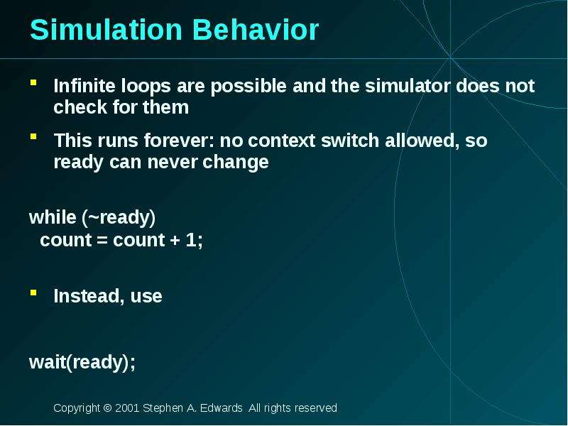
Simulation Behavior Infinite loops are possible and the simulator does not check for them This runs forever: no context switch allowed, so ready can...
Описание слайда:
Simulation Behavior Infinite loops are possible and the simulator does not check for them This runs forever: no context switch allowed, so ready can never change while (~ready) count = count + 1; Instead, use wait(ready);

Слайд 47


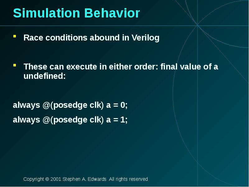
Simulation Behavior Race conditions abound in Verilog These can execute in either order: final value of a undefined: always @(posedge clk) a = 0;...
Описание слайда:
Simulation Behavior Race conditions abound in Verilog These can execute in either order: final value of a undefined: always @(posedge clk) a = 0; always @(posedge clk) a = 1;

Слайд 48


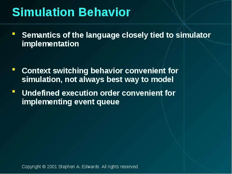
Simulation Behavior Semantics of the language closely tied to simulator implementation Context switching behavior convenient for simulation, not...
Описание слайда:
Simulation Behavior Semantics of the language closely tied to simulator implementation Context switching behavior convenient for simulation, not always best way to model Undefined execution order convenient for implementing event queue

Слайд 49


Verilog and Logic Synthesis
Описание слайда:
Verilog and Logic Synthesis

Слайд 50


Logic Synthesis Verilog is used in two ways Model for discrete-event simulation Specification for a logic synthesis system Logic synthesis converts a...
Описание слайда:
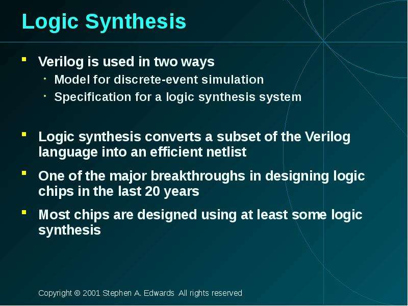
Logic Synthesis Verilog is used in two ways Model for discrete-event simulation Specification for a logic synthesis system Logic synthesis converts a subset of the Verilog language into an efficient netlist One of the major breakthroughs in designing logic chips in the last 20 years Most chips are designed using at least some logic synthesis

Слайд 51


Logic Synthesis Takes place in two stages: Translation of Verilog (or VHDL) source to a netlist Register inference Optimization of the resulting...
Описание слайда:
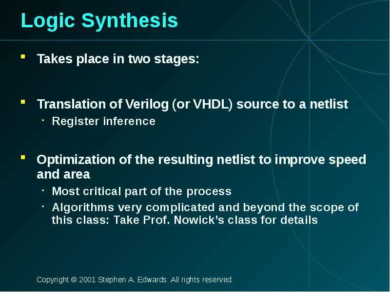
Logic Synthesis Takes place in two stages: Translation of Verilog (or VHDL) source to a netlist Register inference Optimization of the resulting netlist to improve speed and area Most critical part of the process Algorithms very complicated and beyond the scope of this class: Take Prof. Nowick’s class for details

Слайд 52


Translating Verilog into Gates Parts of the language easy to translate Structural descriptions with primitives Already a netlist Continuous...
Описание слайда:
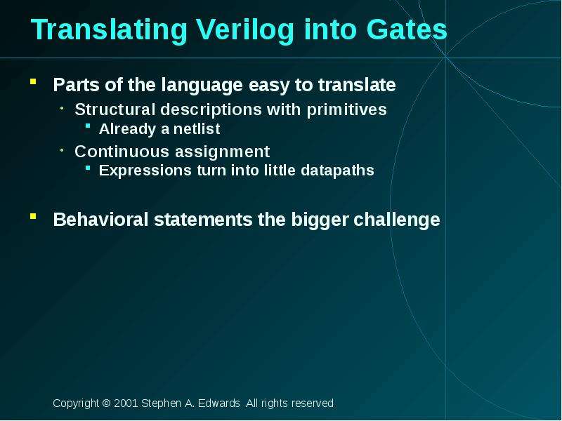
Translating Verilog into Gates Parts of the language easy to translate Structural descriptions with primitives Already a netlist Continuous assignment Expressions turn into little datapaths Behavioral statements the bigger challenge

Слайд 53


What Can Be Translated Structural definitions Everything Behavioral blocks Depends on sensitivity list Only when they have reasonable interpretation...
Описание слайда:
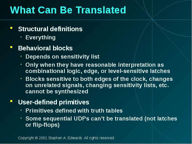
What Can Be Translated Structural definitions Everything Behavioral blocks Depends on sensitivity list Only when they have reasonable interpretation as combinational logic, edge, or level-sensitive latches Blocks sensitive to both edges of the clock, changes on unrelated signals, changing sensitivity lists, etc. cannot be synthesized User-defined primitives Primitives defined with truth tables Some sequential UDPs can’t be translated (not latches or flip-flops)

Слайд 54


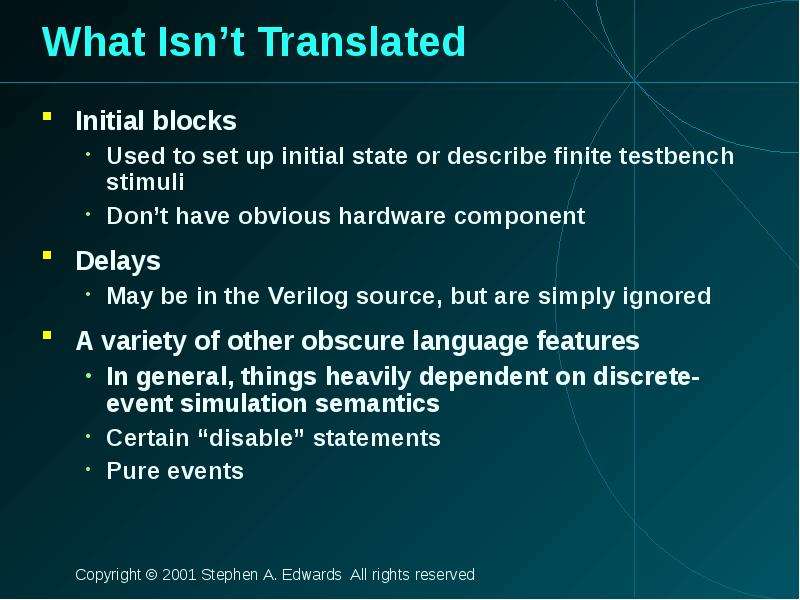
What Isn’t Translated Initial blocks Used to set up initial state or describe finite testbench stimuli Don’t have obvious hardware component Delays...
Описание слайда:
What Isn’t Translated Initial blocks Used to set up initial state or describe finite testbench stimuli Don’t have obvious hardware component Delays May be in the Verilog source, but are simply ignored A variety of other obscure language features In general, things heavily dependent on discrete-event simulation semantics Certain “disable” statements Pure events

Слайд 55


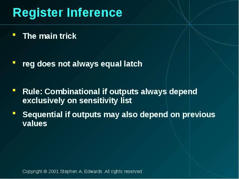
Register Inference The main trick reg does not always equal latch Rule: Combinational if outputs always depend exclusively on sensitivity list...
Описание слайда:
Register Inference The main trick reg does not always equal latch Rule: Combinational if outputs always depend exclusively on sensitivity list Sequential if outputs may also depend on previous values

Слайд 56


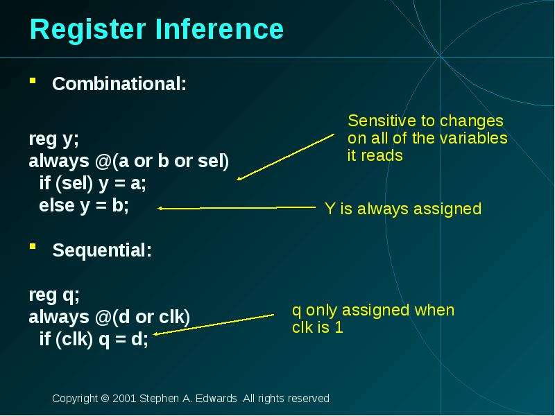
Register Inference Combinational: reg y; always @(a or b or sel) if (sel) y = a; else y = b; Sequential: reg q; always @(d or clk) if (clk) q = d;
Описание слайда:
Register Inference Combinational: reg y; always @(a or b or sel) if (sel) y = a; else y = b; Sequential: reg q; always @(d or clk) if (clk) q = d;

Слайд 57


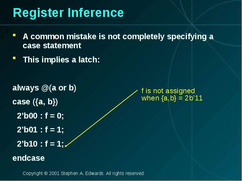
Register Inference A common mistake is not completely specifying a case statement This implies a latch: always @(a or b) case ({a, b}) 2’b00 : f = 0;...
Описание слайда:
Register Inference A common mistake is not completely specifying a case statement This implies a latch: always @(a or b) case ({a, b}) 2’b00 : f = 0; 2’b01 : f = 1; 2’b10 : f = 1; endcase

Слайд 58


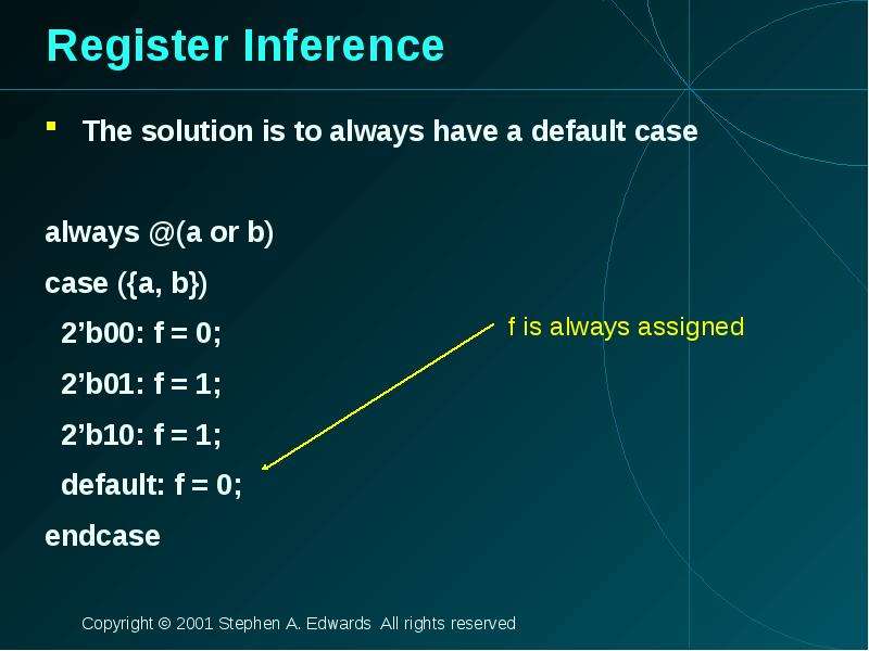
Register Inference The solution is to always have a default case always @(a or b) case ({a, b}) 2’b00: f = 0; 2’b01: f = 1; 2’b10: f = 1; default: f...
Описание слайда:
Register Inference The solution is to always have a default case always @(a or b) case ({a, b}) 2’b00: f = 0; 2’b01: f = 1; 2’b10: f = 1; default: f = 0; endcase

Слайд 59


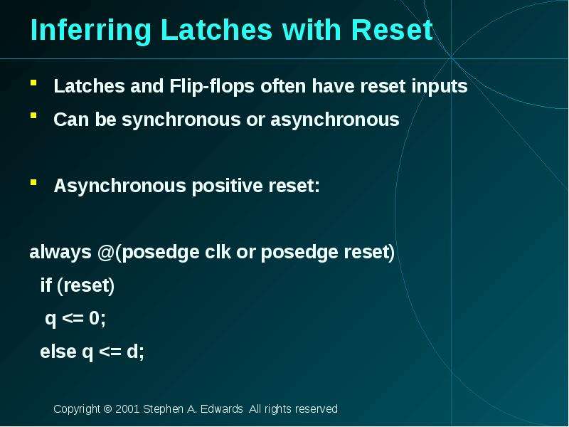
Inferring Latches with Reset Latches and Flip-flops often have reset inputs Can be synchronous or asynchronous Asynchronous positive reset: always...
Описание слайда:
Inferring Latches with Reset Latches and Flip-flops often have reset inputs Can be synchronous or asynchronous Asynchronous positive reset: always @(posedge clk or posedge reset) if (reset) q

Слайд 60


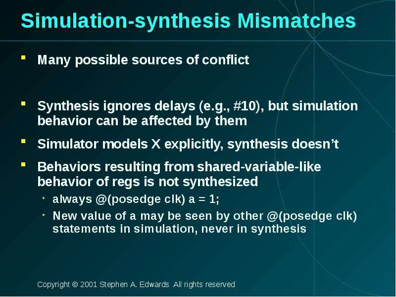
Simulation-synthesis Mismatches Many possible sources of conflict Synthesis ignores delays (e.g., #10), but simulation behavior can be affected by...
Описание слайда:
Simulation-synthesis Mismatches Many possible sources of conflict Synthesis ignores delays (e.g., #10), but simulation behavior can be affected by them Simulator models X explicitly, synthesis doesn’t Behaviors resulting from shared-variable-like behavior of regs is not synthesized always @(posedge clk) a = 1; New value of a may be seen by other @(posedge clk) statements in simulation, never in synthesis

Слайд 61


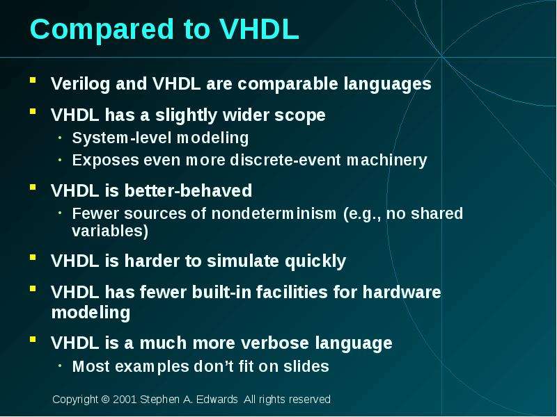
Compared to VHDL Verilog and VHDL are comparable languages VHDL has a slightly wider scope System-level modeling Exposes even more discrete-event...
Описание слайда:
Compared to VHDL Verilog and VHDL are comparable languages VHDL has a slightly wider scope System-level modeling Exposes even more discrete-event machinery VHDL is better-behaved Fewer sources of nondeterminism (e.g., no shared variables) VHDL is harder to simulate quickly VHDL has fewer built-in facilities for hardware modeling VHDL is a much more verbose language Most examples don’t fit on slides


Теги Verilog Language
Похожие презентации
Mypresentation.ru
Загрузить презентацию