🗊Презентация Axles and shafts

Категория: Физика
Нажмите для полного просмотра!
Axles and shafts, слайд №1Axles and shafts, слайд №2Axles and shafts, слайд №3Axles and shafts, слайд №4Axles and shafts, слайд №5Axles and shafts, слайд №6Axles and shafts, слайд №7Axles and shafts, слайд №8Axles and shafts, слайд №9Axles and shafts, слайд №10Axles and shafts, слайд №11Axles and shafts, слайд №12Axles and shafts, слайд №13Axles and shafts, слайд №14Axles and shafts, слайд №15Axles and shafts, слайд №16Axles and shafts, слайд №17Axles and shafts, слайд №18Axles and shafts, слайд №19Axles and shafts, слайд №20Axles and shafts, слайд №21Axles and shafts, слайд №22Axles and shafts, слайд №23Axles and shafts, слайд №24Axles and shafts, слайд №25Axles and shafts, слайд №26Axles and shafts, слайд №27Axles and shafts, слайд №28Axles and shafts, слайд №29Axles and shafts, слайд №30Axles and shafts, слайд №31Axles and shafts, слайд №32Axles and shafts, слайд №33Axles and shafts, слайд №34Axles and shafts, слайд №35Axles and shafts, слайд №36Axles and shafts, слайд №37Axles and shafts, слайд №38

Содержание
Вы можете ознакомиться и скачать презентацию на тему Axles and shafts. Доклад-сообщение содержит 38 слайдов. Презентации для любого класса можно скачать бесплатно. Если материал и наш сайт презентаций Mypresentation Вам понравились – поделитесь им с друзьями с помощью социальных кнопок и добавьте в закладки в своем браузере.
Слайды и текст этой презентации


Слайд 1


AXLES AND SHAFTS
Описание слайда:
AXLES AND SHAFTS

Слайд 2


AXLES AND SHAFTS
Links intended to carry rotating elements (pulleys, sprockets, pinions, gears, half-couplings, etc.) are called as axles or shafts.
Описание слайда:
AXLES AND SHAFTS Links intended to carry rotating elements (pulleys, sprockets, pinions, gears, half-couplings, etc.) are called as axles or shafts.

Слайд 3


AXLES
Axles are intended to support rotating parts that do not transmit torques and are subjected to bending only.
Описание слайда:
AXLES Axles are intended to support rotating parts that do not transmit torques and are subjected to bending only.

Слайд 4


SHAFTS
Shafts are designed to carry links which transmit torques and experience both bending and torsion.
Описание слайда:
SHAFTS Shafts are designed to carry links which transmit torques and experience both bending and torsion.

Слайд 5


CLASSIFICATION OF SHAFTS
According to purpose
Shafts of various drives (gear drives, belt drives, chain drives and so on);
Main shafts of mechanisms and machines whose function is to carry not only drive elements but other elements that do not transmit torques such as rotors, fly-wheels, turbine disks, etc.
Описание слайда:
CLASSIFICATION OF SHAFTS According to purpose Shafts of various drives (gear drives, belt drives, chain drives and so on); Main shafts of mechanisms and machines whose function is to carry not only drive elements but other elements that do not transmit torques such as rotors, fly-wheels, turbine disks, etc.

Слайд 6


CLASSIFICATION OF SHAFTS
2. According to the shape
Straight shafts; 
Cranked shafts;
Flexible shafts.
Описание слайда:
CLASSIFICATION OF SHAFTS 2. According to the shape Straight shafts; Cranked shafts; Flexible shafts.

Слайд 7


CLASSIFICATION OF SHAFTS
3. According to the construction
Shafts of constant cross section (without steps);
Shafts of variable cross section (of stepped configuration);
Shafts made solid with gears or worms.
Описание слайда:
CLASSIFICATION OF SHAFTS 3. According to the construction Shafts of constant cross section (without steps); Shafts of variable cross section (of stepped configuration); Shafts made solid with gears or worms.

Слайд 8


CLASSIFICATION OF SHAFTS
4. According to the shape of the cross section
Shafts with solid circular cross section;
Shafts with hollow circular cross section;
Shafts with keyways;
Shafts with splines;
Shafts with rectangular cross section.
Описание слайда:
CLASSIFICATION OF SHAFTS 4. According to the shape of the cross section Shafts with solid circular cross section; Shafts with hollow circular cross section; Shafts with keyways; Shafts with splines; Shafts with rectangular cross section.

Слайд 9


SHAFTS
Portion of the shaft which is in contact with a bearing is called journal. We will distinguish between end journal, neck journal and thrust journal.
Описание слайда:
SHAFTS Portion of the shaft which is in contact with a bearing is called journal. We will distinguish between end journal, neck journal and thrust journal.

Слайд 10


CALCULATION OF SHAFTS
 Strength;

 Rigidity;

 Oscillations.
Описание слайда:
CALCULATION OF SHAFTS Strength; Rigidity; Oscillations.

Слайд 11


CALCULATION OF SHAFTS 
FOR STRENGTH
Determination of the minimum diameter of the shaft;
Designing the shaft construction;
Strength analysis of the shaft.
Описание слайда:
CALCULATION OF SHAFTS FOR STRENGTH Determination of the minimum diameter of the shaft; Designing the shaft construction; Strength analysis of the shaft.

Слайд 12


DETERMINATION OF THE MINIMUM DIAMETER OF THE SHAFT
Minimum diameter of the shaft is determined taking into account torsion stresses only. In order to compensate neglect of bending stresses the allowable torsion stress is assumed as down rated ([=20…40 MPa).
Описание слайда:
DETERMINATION OF THE MINIMUM DIAMETER OF THE SHAFT Minimum diameter of the shaft is determined taking into account torsion stresses only. In order to compensate neglect of bending stresses the allowable torsion stress is assumed as down rated ([=20…40 MPa).

Слайд 13


DESIGNING THE SHAFT CONSTRUCTION
Input shaft
Описание слайда:
DESIGNING THE SHAFT CONSTRUCTION Input shaft

Слайд 14


SEALS
Seals are divided into:
Commercial seals  (Lip-type  seals);
Labyrinth seals;
Groove seals;
Combined seals.
Описание слайда:
SEALS Seals are divided into: Commercial seals (Lip-type seals); Labyrinth seals; Groove seals; Combined seals.

Слайд 15


DESIGNING THE SHAFT CONSTRUCTION 
Input bevel pinion shaft
Описание слайда:
DESIGNING THE SHAFT CONSTRUCTION Input bevel pinion shaft

Слайд 16


DESIGNING THE SHAFT CONSTRUCTION 
Intermediate shaft
Описание слайда:
DESIGNING THE SHAFT CONSTRUCTION Intermediate shaft

Слайд 17


DESIGNING THE SHAFT CONSTRUCTION
Output shaft
Описание слайда:
DESIGNING THE SHAFT CONSTRUCTION Output shaft

Слайд 18


SPUR GEAR
Thickness of the rim                       δ = (3…4)·m;
Thickness of the web                     C = (0.2…0.3)·bg;
Diameter of the hub                      dhub=(1.5…1.7)·dshaft;
Length of the hub                          lhub=(1.2…1.5)·dshaft;
Diameter of the hole  
      dhole=(D0-dhub)/4;
Diameter of the hole centre line 
      Dc=(D0+dhub)/4;  ;
Fillet radii  R ≥ 6 mm; 
Angle γ ≥ 7º.
Описание слайда:
SPUR GEAR Thickness of the rim δ = (3…4)·m; Thickness of the web C = (0.2…0.3)·bg; Diameter of the hub dhub=(1.5…1.7)·dshaft; Length of the hub lhub=(1.2…1.5)·dshaft; Diameter of the hole dhole=(D0-dhub)/4; Diameter of the hole centre line Dc=(D0+dhub)/4; ; Fillet radii R ≥ 6 mm; Angle γ ≥ 7º.

Слайд 19


WORM GEAR
Thickness of the bronze ring     δ1= 2·m;
Thickness of the steel rim         δ2= 2·m;
Thickness of the web      C = 0.2…0.3)·bg;
Diameter of the hub    dhub=(1.5…1.7)·dshaft;
Length of the hub         lhub=(1.2…1.5)·dshaft;
Diameter  of the screw  ds=(1.2…1.4)·m;
Length of the screw     ls=(0.3…0.4)·bg;
Diameter of the hole    dhole=(D0-dhub)/4;
Diameter of the hole centre line 
      Dc=(D0+dhub)/4;
Width and height of the collar                           
      h = 0.15·bg; t = 0.8·h  ;
Fillet radii  R ≥ 6 mm 
Angle γ ≥ 7º.
Описание слайда:
WORM GEAR Thickness of the bronze ring δ1= 2·m; Thickness of the steel rim δ2= 2·m; Thickness of the web C = 0.2…0.3)·bg; Diameter of the hub dhub=(1.5…1.7)·dshaft; Length of the hub lhub=(1.2…1.5)·dshaft; Diameter of the screw ds=(1.2…1.4)·m; Length of the screw ls=(0.3…0.4)·bg; Diameter of the hole dhole=(D0-dhub)/4; Diameter of the hole centre line Dc=(D0+dhub)/4; Width and height of the collar h = 0.15·bg; t = 0.8·h ; Fillet radii R ≥ 6 mm Angle γ ≥ 7º.

Слайд 20


SKETCH  LAYOUT
Double stage spur gear speed reducer
Описание слайда:
SKETCH LAYOUT Double stage spur gear speed reducer

Слайд 21


SKETCH  LAYOUT
Double stage coaxial spur gear speed reducer
Описание слайда:
SKETCH LAYOUT Double stage coaxial spur gear speed reducer

Слайд 22


SKETCH  LAYOUT
Bevel gears
Описание слайда:
SKETCH LAYOUT Bevel gears

Слайд 23


SKETCH  LAYOUT
Double stage bevel and spur gear speed reducer
Описание слайда:
SKETCH LAYOUT Double stage bevel and spur gear speed reducer

Слайд 24


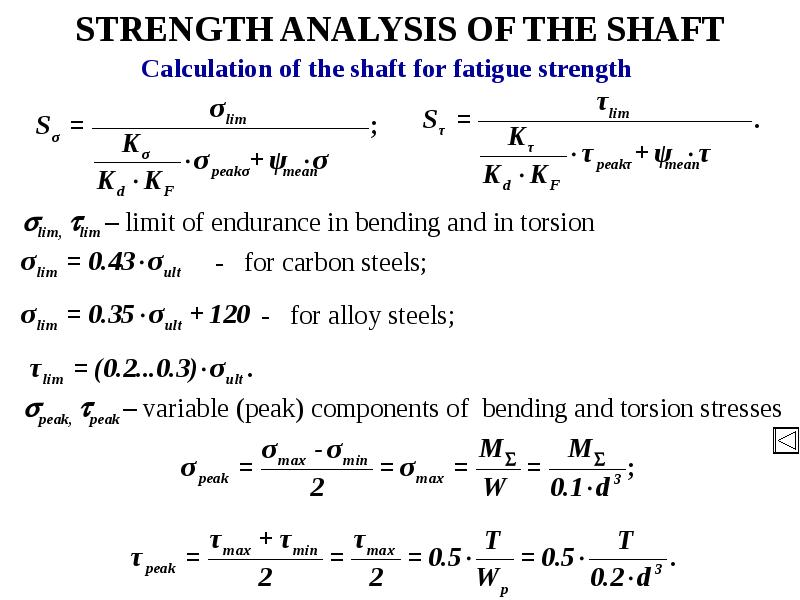
STRENGTH ANALYSIS OF THE SHAFT
Описание слайда:
STRENGTH ANALYSIS OF THE SHAFT

Слайд 25


STRENGTH ANALYSIS OF THE SHAFT
Описание слайда:
STRENGTH ANALYSIS OF THE SHAFT

Слайд 26


STRENGTH ANALYSIS OF THE SHAFT
Checking:
Описание слайда:
STRENGTH ANALYSIS OF THE SHAFT Checking:

Слайд 27


STRENGTH ANALYSIS OF THE SHAFT
T
Описание слайда:
STRENGTH ANALYSIS OF THE SHAFT T

Слайд 28


STRENGTH ANALYSIS OF THE SHAFT
Calculation of the shaft for fatigue strength
Описание слайда:
STRENGTH ANALYSIS OF THE SHAFT Calculation of the shaft for fatigue strength

Слайд 29


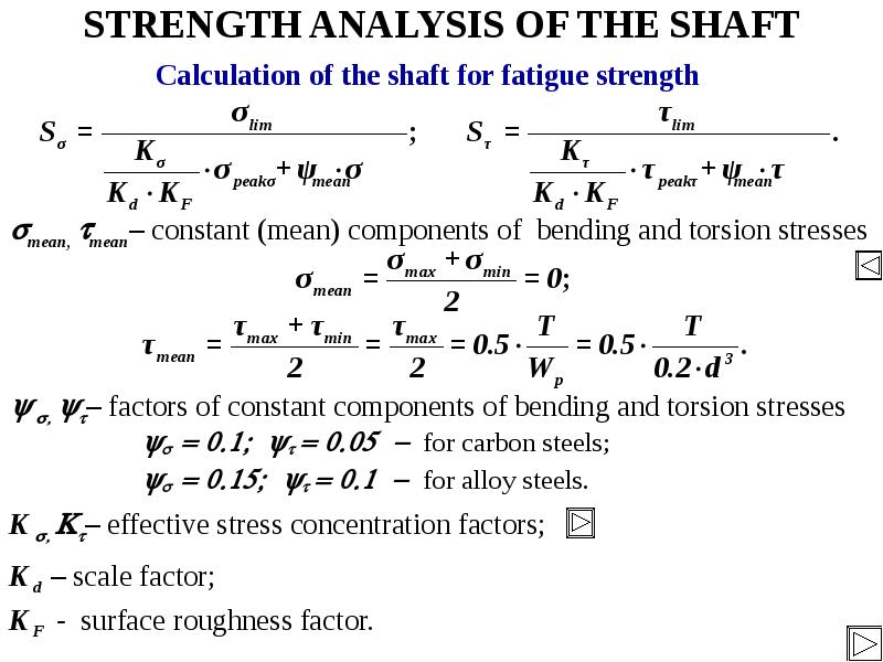
STRENGTH ANALYSIS OF THE SHAFT
Calculation of the shaft for fatigue strength
Описание слайда:
STRENGTH ANALYSIS OF THE SHAFT Calculation of the shaft for fatigue strength

Слайд 30


STRENGTH ANALYSIS OF THE SHAFT
for carbon steels; 
for alloy steels.
Описание слайда:
STRENGTH ANALYSIS OF THE SHAFT for carbon steels; for alloy steels.

Слайд 31


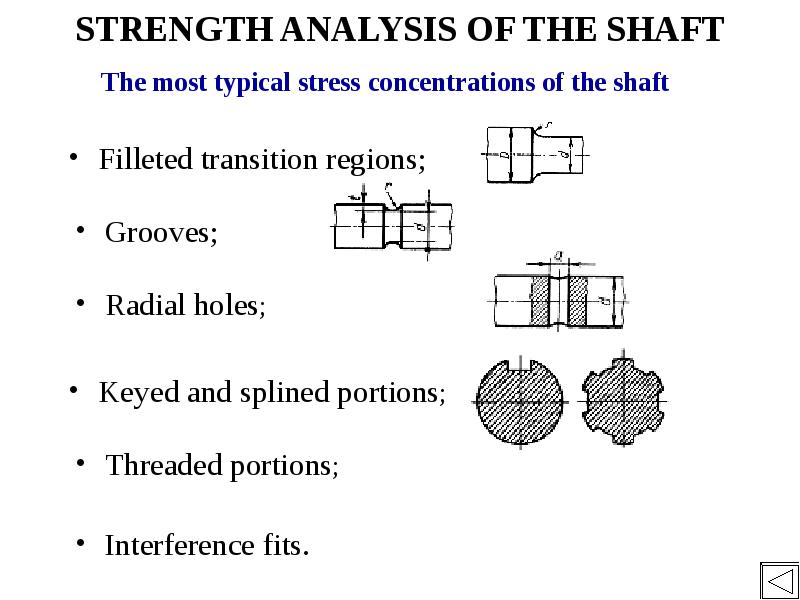
STRENGTH ANALYSIS OF THE SHAFT
The most typical stress concentrations of the shaft
Описание слайда:
STRENGTH ANALYSIS OF THE SHAFT The most typical stress concentrations of the shaft

Слайд 32


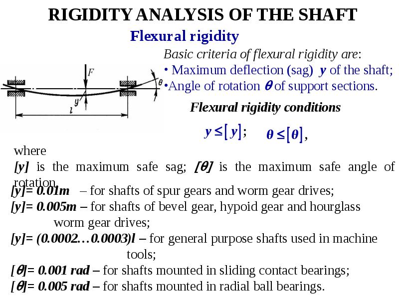
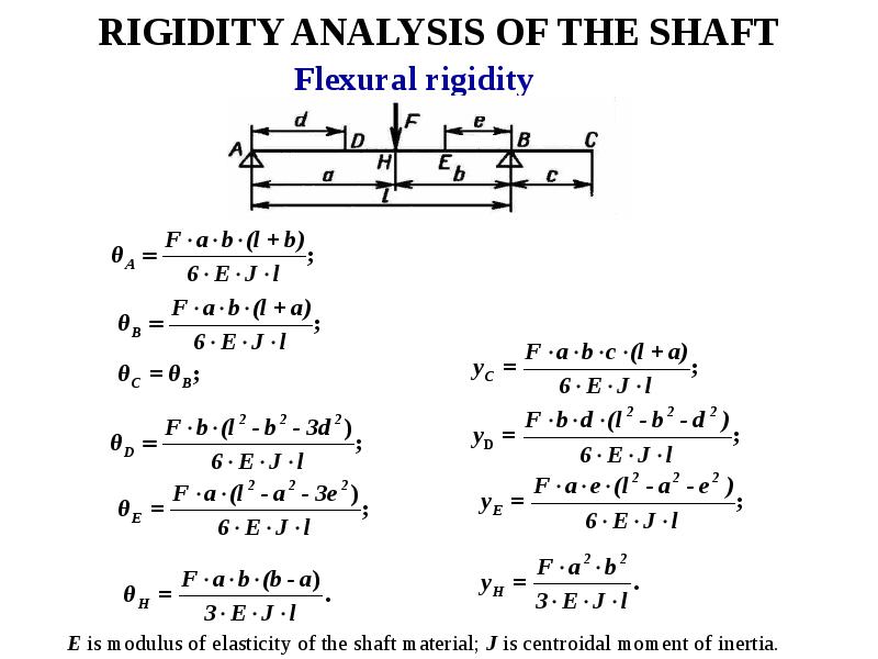
RIGIDITY ANALYSIS OF THE SHAFT
Flexural rigidity
Описание слайда:
RIGIDITY ANALYSIS OF THE SHAFT Flexural rigidity

Слайд 33


RIGIDITY ANALYSIS OF THE SHAFT
Описание слайда:
RIGIDITY ANALYSIS OF THE SHAFT

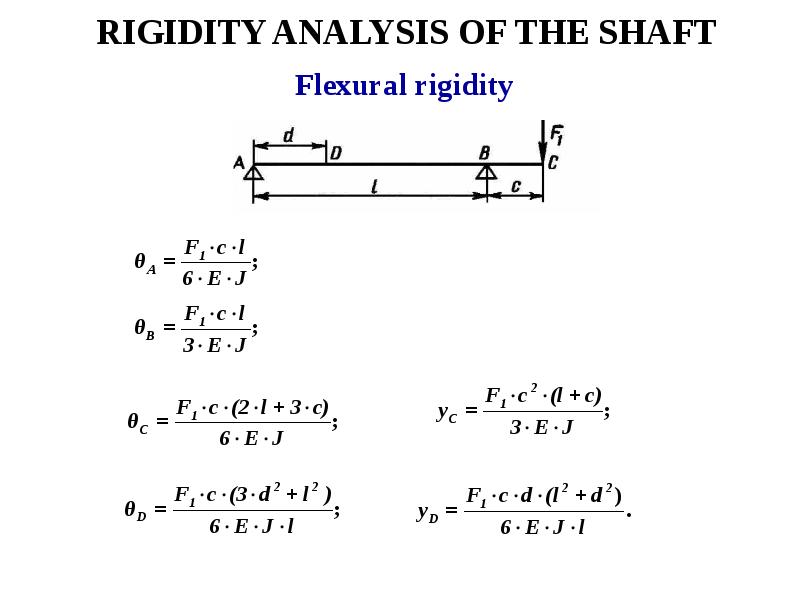
Слайд 34


RIGIDITY ANALYSIS OF THE SHAFT
Описание слайда:
RIGIDITY ANALYSIS OF THE SHAFT

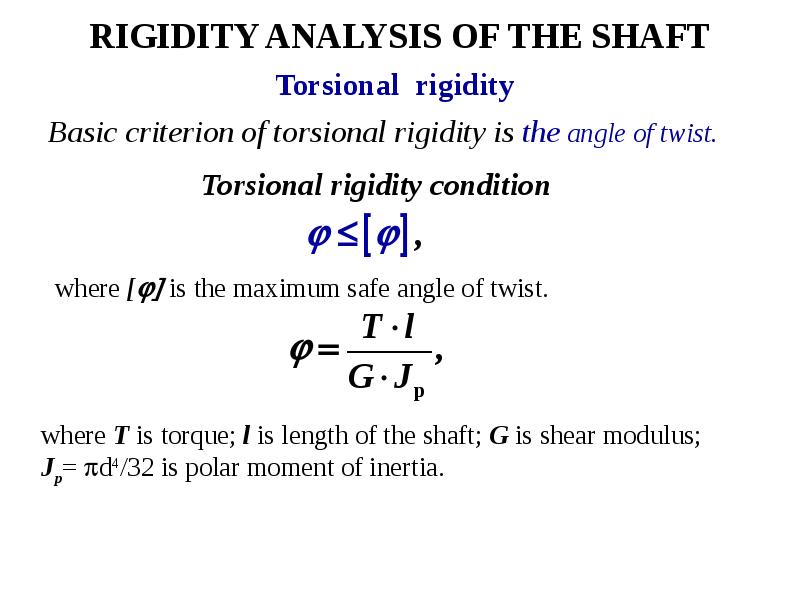
Слайд 35


RIGIDITY ANALYSIS OF THE SHAFT
Basic criterion of torsional rigidity is the angle of twist.
Описание слайда:
RIGIDITY ANALYSIS OF THE SHAFT Basic criterion of torsional rigidity is the angle of twist.

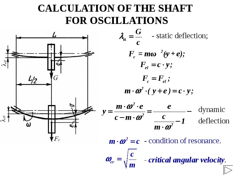
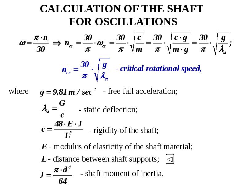
Слайд 36


CALCULATION OF THE SHAFT 
FOR OSCILLATIONS
- static deflection;
Описание слайда:
CALCULATION OF THE SHAFT FOR OSCILLATIONS - static deflection;

Слайд 37


CALCULATION OF THE SHAFT 
FOR OSCILLATIONS
- critical rotational speed,
Описание слайда:
CALCULATION OF THE SHAFT FOR OSCILLATIONS - critical rotational speed,

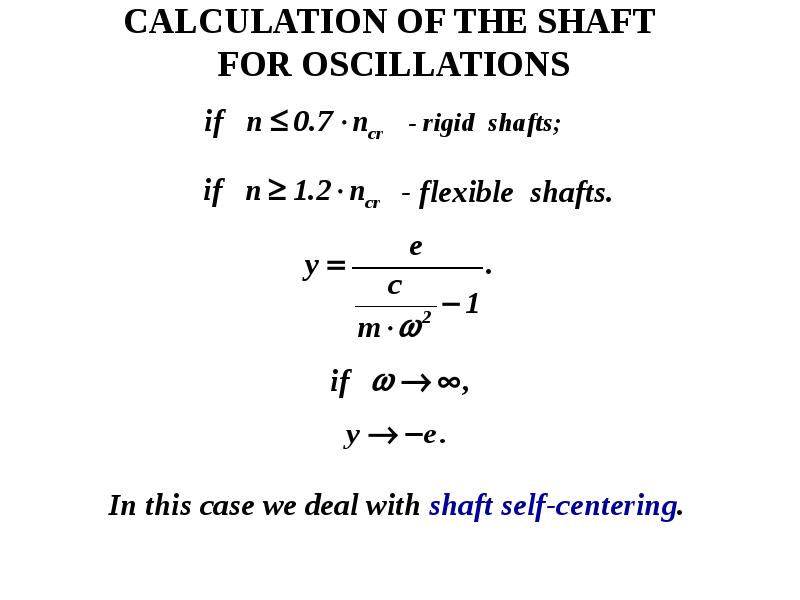
Слайд 38


CALCULATION OF THE SHAFT 
FOR OSCILLATIONS
- rigid  shafts;
Описание слайда:
CALCULATION OF THE SHAFT FOR OSCILLATIONS - rigid shafts;


Теги Axles and shafts
Похожие презентации
Mypresentation.ru
Загрузить презентацию