🗊Презентация Cathode Ray Oscilloscope

Категория: Физика
Нажмите для полного просмотра!
Cathode Ray Oscilloscope, слайд №1Cathode Ray Oscilloscope, слайд №2Cathode Ray Oscilloscope, слайд №3Cathode Ray Oscilloscope, слайд №4Cathode Ray Oscilloscope, слайд №5Cathode Ray Oscilloscope, слайд №6Cathode Ray Oscilloscope, слайд №7Cathode Ray Oscilloscope, слайд №8Cathode Ray Oscilloscope, слайд №9Cathode Ray Oscilloscope, слайд №10Cathode Ray Oscilloscope, слайд №11Cathode Ray Oscilloscope, слайд №12Cathode Ray Oscilloscope, слайд №13Cathode Ray Oscilloscope, слайд №14Cathode Ray Oscilloscope, слайд №15Cathode Ray Oscilloscope, слайд №16Cathode Ray Oscilloscope, слайд №17Cathode Ray Oscilloscope, слайд №18Cathode Ray Oscilloscope, слайд №19Cathode Ray Oscilloscope, слайд №20Cathode Ray Oscilloscope, слайд №21Cathode Ray Oscilloscope, слайд №22Cathode Ray Oscilloscope, слайд №23Cathode Ray Oscilloscope, слайд №24Cathode Ray Oscilloscope, слайд №25Cathode Ray Oscilloscope, слайд №26Cathode Ray Oscilloscope, слайд №27Cathode Ray Oscilloscope, слайд №28Cathode Ray Oscilloscope, слайд №29Cathode Ray Oscilloscope, слайд №30Cathode Ray Oscilloscope, слайд №31Cathode Ray Oscilloscope, слайд №32Cathode Ray Oscilloscope, слайд №33

Вы можете ознакомиться и скачать презентацию на тему Cathode Ray Oscilloscope. Доклад-сообщение содержит 33 слайдов. Презентации для любого класса можно скачать бесплатно. Если материал и наш сайт презентаций Mypresentation Вам понравились – поделитесь им с друзьями с помощью социальных кнопок и добавьте в закладки в своем браузере.

Слайды и текст этой презентации


Слайд 1


Cathode Ray Oscilloscope
Описание слайда:
Cathode Ray Oscilloscope

Слайд 2


What is an Oscilloscope?
Oscilloscopes are very fast X-Y plotters, displaying an input signal versus time. 
The stylus of this plotter is a luminous spot which moves over the display area in response to an input voltage. 
The luminous spot is produced by a beam of electrons striking a fluorescent screen. The extremely low inertia associated with a beam of electrons enables such a beam to be used following the changes in instantaneous values of rapidly varying voltages.
It is  used for displaying, measurement, and analysis of waveform such as peak value, rise time, fall time, frequency, phase difference, pulse width.
Описание слайда:
What is an Oscilloscope? Oscilloscopes are very fast X-Y plotters, displaying an input signal versus time. The stylus of this plotter is a luminous spot which moves over the display area in response to an input voltage. The luminous spot is produced by a beam of electrons striking a fluorescent screen. The extremely low inertia associated with a beam of electrons enables such a beam to be used following the changes in instantaneous values of rapidly varying voltages. It is used for displaying, measurement, and analysis of waveform such as peak value, rise time, fall time, frequency, phase difference, pulse width.

Слайд 3


Block diagram of CRT oscilloscope
Описание слайда:
Block diagram of CRT oscilloscope

Слайд 4


How does CR Oscilloscope work?
The normal form of a CRO uses a horizontal input voltage which is an internally generated ramp voltage called ‘time base’  applied to the horizontal deflecting plates. The horizontal voltage moves the luminous spot periodically in a horizontal direction from left to right over the display area or screen.
 The vertical input to the CRO is the voltage under investigation which is applied to the vertical deflecting plates. The vertical input voltage moves the luminous spot up and down  according  to the instantaneous value of the voltage. 
The luminous spot thus traces the waveform of the input voltage with respect to time. When the input voltage repeats itself at a fast rate, the display on the screen appears stationary on the screen.
Описание слайда:
How does CR Oscilloscope work? The normal form of a CRO uses a horizontal input voltage which is an internally generated ramp voltage called ‘time base’ applied to the horizontal deflecting plates. The horizontal voltage moves the luminous spot periodically in a horizontal direction from left to right over the display area or screen. The vertical input to the CRO is the voltage under investigation which is applied to the vertical deflecting plates. The vertical input voltage moves the luminous spot up and down according to the instantaneous value of the voltage. The luminous spot thus traces the waveform of the input voltage with respect to time. When the input voltage repeats itself at a fast rate, the display on the screen appears stationary on the screen.

Слайд 5


Construction of Cathode Ray Tube
Описание слайда:
Construction of Cathode Ray Tube

Слайд 6


Triode Section
The triode section of the tube consists of a cathode, a grid, and an anode.
 The grid, which is a nickel cup with a hole in it, almost completely encloses the cathode. 
The cathode (made of nickel), is cylinder shaped with a flat, oxide-coated, electron emitting surface directed toward the hole in the grid. 
Cathode heating is provided by an inside filament. 
The cathode is typically held at approximately -2 kV, and the grid potential is adjustable from approximately -2000 V to -2050 V. 
The grid-cathode potential controls the number of electrons directed to the screen. 
A large number of electrons striking one point will cause the screen to glow brightly; a small number will produce a dim glow.
Therefore, the grid potential control the brightness  of the trace.
Описание слайда:
Triode Section The triode section of the tube consists of a cathode, a grid, and an anode. The grid, which is a nickel cup with a hole in it, almost completely encloses the cathode. The cathode (made of nickel), is cylinder shaped with a flat, oxide-coated, electron emitting surface directed toward the hole in the grid. Cathode heating is provided by an inside filament. The cathode is typically held at approximately -2 kV, and the grid potential is adjustable from approximately -2000 V to -2050 V. The grid-cathode potential controls the number of electrons directed to the screen. A large number of electrons striking one point will cause the screen to glow brightly; a small number will produce a dim glow. Therefore, the grid potential control the brightness of the trace.

Слайд 7


Focusing Section
The first anode (A1) is cylinder shaped, open at one end and closed at the other end, with a hole at the center of the closed end. 
Since A1 is grounded and the cathode is at a high negative potential, A1 is highly positive with respect to the cathode. This causes electrons to be accelerated from the cathode through the holes in the grid and anode to the focusing section of the tube. 
The focusing electrodes A1, A2, and A3 are sometimes referred to as an electron lens. 
The function of the electron lens is to focus the electrons to a fine point on the screen. 
A1 provides the accelerating field to draw the electrons from the cathode, and the hole in A1 limits the initial cross section of the electron beam. 
A3 and A1 are held at ground potential while the A2  potential is adjustable around -2 kV.
Описание слайда:
Focusing Section The first anode (A1) is cylinder shaped, open at one end and closed at the other end, with a hole at the center of the closed end. Since A1 is grounded and the cathode is at a high negative potential, A1 is highly positive with respect to the cathode. This causes electrons to be accelerated from the cathode through the holes in the grid and anode to the focusing section of the tube. The focusing electrodes A1, A2, and A3 are sometimes referred to as an electron lens. The function of the electron lens is to focus the electrons to a fine point on the screen. A1 provides the accelerating field to draw the electrons from the cathode, and the hole in A1 limits the initial cross section of the electron beam. A3 and A1 are held at ground potential while the A2 potential is adjustable around -2 kV.

Слайд 8


Deflection Section
Описание слайда:
Deflection Section

Слайд 9


Deflection Section
When one plate of a pair of deflecting plates has a positive voltage applied to it, and the other one has a negative potential, the electrons in the beam are attracted toward the positive plate and repelled from the negative plate. The electrons are actually accelerated in the direction of the positive plate.
The tube sensitivity to deflecting voltages can be expressed in two ways. The voltage required to produce one division of deflection at the screen (V/cm) is referred to as the deflection factor of the tube. The deflection produced by 1 V (cm/V) is referred to as the deflection sensitivity.
Описание слайда:
Deflection Section When one plate of a pair of deflecting plates has a positive voltage applied to it, and the other one has a negative potential, the electrons in the beam are attracted toward the positive plate and repelled from the negative plate. The electrons are actually accelerated in the direction of the positive plate. The tube sensitivity to deflecting voltages can be expressed in two ways. The voltage required to produce one division of deflection at the screen (V/cm) is referred to as the deflection factor of the tube. The deflection produced by 1 V (cm/V) is referred to as the deflection sensitivity.

Слайд 10


Deflection Amplifiers
Описание слайда:
Deflection Amplifiers

Слайд 11


Deflection Amplifiers
  When the input voltage to the attenuator is zero, the base of Q1 is at ground level. If Q4 base is also adjusted to ground level, Q2 and Q3 bases are both at the same negative potential with respect to ground 
(-VB2 = -VB3). Also, IC2 = IC3 and the voltage drops across R3 and R6 set the collectors of Q2 and Q3 at ground level. These collectors are the amplifier outputs, and they are connected directly to the deflection plates.
Описание слайда:
Deflection Amplifiers When the input voltage to the attenuator is zero, the base of Q1 is at ground level. If Q4 base is also adjusted to ground level, Q2 and Q3 bases are both at the same negative potential with respect to ground (-VB2 = -VB3). Also, IC2 = IC3 and the voltage drops across R3 and R6 set the collectors of Q2 and Q3 at ground level. These collectors are the amplifier outputs, and they are connected directly to the deflection plates.

Слайд 12


Deflection Amplifiers
Описание слайда:
Deflection Amplifiers

Слайд 13


Waveform display
If a constantly increasing (ramp) voltage is also applied to the horizontal deflecting plates, then, as well as moving vertically, the spot on the tube face moves horizontally.
Описание слайда:
Waveform display If a constantly increasing (ramp) voltage is also applied to the horizontal deflecting plates, then, as well as moving vertically, the spot on the tube face moves horizontally.

Слайд 14


Waveform display
Описание слайда:
Waveform display

Слайд 15


Oscilloscope time base
Horizontal Sweep Generator
Описание слайда:
Oscilloscope time base Horizontal Sweep Generator

Слайд 16


Horizontal Sweep Generator 
The sweep generator consists of two major components: a ramp generator and a non-inverting Schmitt trigger circuit. 
The ramp generator consists of Q1 which is a constant current source. The capacitor (C1) which is selected by S1 switch is charged by the collector current of Q1. Hence a ramp voltage is generated across C1.
Описание слайда:
Horizontal Sweep Generator The sweep generator consists of two major components: a ramp generator and a non-inverting Schmitt trigger circuit. The ramp generator consists of Q1 which is a constant current source. The capacitor (C1) which is selected by S1 switch is charged by the collector current of Q1. Hence a ramp voltage is generated across C1.

Слайд 17


Schmitt trigger circuit
Because the op-amp has a very large voltage gain (typically 200000), a very small difference between the inverting and non-inverting terminals causes the Schmitt output to be saturated. This means that the output voltage is very close to either the positive or the negative supply voltages. Typically, the saturated output voltage is
     +(VCC -1V), or - (VEE - 1V).
Описание слайда:
Schmitt trigger circuit Because the op-amp has a very large voltage gain (typically 200000), a very small difference between the inverting and non-inverting terminals causes the Schmitt output to be saturated. This means that the output voltage is very close to either the positive or the negative supply voltages. Typically, the saturated output voltage is +(VCC -1V), or - (VEE - 1V).

Слайд 18


Horizontal Sweep Generator
Описание слайда:
Horizontal Sweep Generator

Слайд 19


Automatic Time Base
For a waveform to be displayed correctly on an oscilloscope, it is important that the ramp voltage producing the horizontal sweep begin at the same time the displayed waveform goes positive. 
The ramp wave must be synchronized with the input waveform. If the input and ramp waveforms are not synchronized, the displayed wave will appear to continuously slide off to one side of the screen.
Synchronization is accomplished by means of the sync input to the Schmitt trigger in the previous figure, and by the other components of the automatic time base in the following figure.
Описание слайда:
Automatic Time Base For a waveform to be displayed correctly on an oscilloscope, it is important that the ramp voltage producing the horizontal sweep begin at the same time the displayed waveform goes positive. The ramp wave must be synchronized with the input waveform. If the input and ramp waveforms are not synchronized, the displayed wave will appear to continuously slide off to one side of the screen. Synchronization is accomplished by means of the sync input to the Schmitt trigger in the previous figure, and by the other components of the automatic time base in the following figure.

Слайд 20


Automatic Time Base
Описание слайда:
Automatic Time Base

Слайд 21


Automatic Time Base
The voltage waveform to be displayed (Vi) is applied to the vertical amplifier and to the time base triggering amplifier. 
Like the vertical amplifier, the triggering amplifier has differential outputs. These provide two identical but antiphase voltage waveforms (VO1 and VO2). In the triggering amplifier the input is amplified so much that its peaks are cut off by saturation of the amplifier output stage. So the output waveforms are almost square.
Описание слайда:
Automatic Time Base The voltage waveform to be displayed (Vi) is applied to the vertical amplifier and to the time base triggering amplifier. Like the vertical amplifier, the triggering amplifier has differential outputs. These provide two identical but antiphase voltage waveforms (VO1 and VO2). In the triggering amplifier the input is amplified so much that its peaks are cut off by saturation of the amplifier output stage. So the output waveforms are almost square.

Слайд 22


Automatic Time Base
One of these waveforms is passed via switch S2 to the input of an inverting Schmitt trigger circuit.
 The Schmitt is designed to have upper and lower trigger points slightly above and below ground. 
With this condition, it is often called (zero-crossing detector) The Schmitt output rapidly goes negative as the input passes the upper trigger point, and positive as the input passes the lower trigger point.
Описание слайда:
Automatic Time Base One of these waveforms is passed via switch S2 to the input of an inverting Schmitt trigger circuit. The Schmitt is designed to have upper and lower trigger points slightly above and below ground. With this condition, it is often called (zero-crossing detector) The Schmitt output rapidly goes negative as the input passes the upper trigger point, and positive as the input passes the lower trigger point.

Слайд 23


Automatic Time Base
The output from the Schmitt circuit is a square waveform exactly in antiphase with the input wave to be displayed. 
This square wave is applied to a differentiating circuit. The output produced by the differentiator is proportional to the rate of change of the square wave. 
During the times that the square wave is at its constant positive level or at its constant negative level, its rate of change is zero. So the differentiator output is zero at these times. 
At the positive-going edge of the square wave, the rate of change is a large positive quantity. 
At the negative-going edge, the rate of change is a large negative quantity. Therefore, the differentiated square wave is a series of positive spikes coinciding with the positive-going edges of the square wave, and negative spikes coinciding with the negative-going edges.
Описание слайда:
Automatic Time Base The output from the Schmitt circuit is a square waveform exactly in antiphase with the input wave to be displayed. This square wave is applied to a differentiating circuit. The output produced by the differentiator is proportional to the rate of change of the square wave. During the times that the square wave is at its constant positive level or at its constant negative level, its rate of change is zero. So the differentiator output is zero at these times. At the positive-going edge of the square wave, the rate of change is a large positive quantity. At the negative-going edge, the rate of change is a large negative quantity. Therefore, the differentiated square wave is a series of positive spikes coinciding with the positive-going edges of the square wave, and negative spikes coinciding with the negative-going edges.

Слайд 24


Automatic Time Base
The spike waveform is now fed to a positive clipper circuit. This is essentially a rectifier circuit that passes the negative spikes but blocks (or clips off) the positive spikes. 
The negative spikes (which coincide with the commencement of each cycle of the original input) are passed via a hold-off circuit to the sync input of  the sweep generator.
Описание слайда:
Automatic Time Base The spike waveform is now fed to a positive clipper circuit. This is essentially a rectifier circuit that passes the negative spikes but blocks (or clips off) the positive spikes. The negative spikes (which coincide with the commencement of each cycle of the original input) are passed via a hold-off circuit to the sync input of the sweep generator.

Слайд 25


Automatic Time Base
It is seen that the train of negative spikes causes the ramp output of the sweep generator to be synchronized with the input waveform that is to be displayed. 
The ramp commences at the beginning of each positive half-cycle of the input. 
The ramp output from the sweep generator is fed to the horizontal deflection amplifier.
Описание слайда:
Automatic Time Base It is seen that the train of negative spikes causes the ramp output of the sweep generator to be synchronized with the input waveform that is to be displayed. The ramp commences at the beginning of each positive half-cycle of the input. The ramp output from the sweep generator is fed to the horizontal deflection amplifier.

Слайд 26


Dual-trace oscilloscopes
Most oscilloscopes can display two waveforms. This allows    waveforms to be compared in terms of amplitude and phase or     time.
Two input terminals and two sets of controls are provided,     identified as channel A and channel B.
The construction of a dual-trace CRT involves two complete    electron guns are contained in a single tube, and the instrument     can be termed as dualbeam oscilloscope.
Описание слайда:
Dual-trace oscilloscopes Most oscilloscopes can display two waveforms. This allows waveforms to be compared in terms of amplitude and phase or time. Two input terminals and two sets of controls are provided, identified as channel A and channel B. The construction of a dual-trace CRT involves two complete electron guns are contained in a single tube, and the instrument can be termed as dualbeam oscilloscope.

Слайд 27


Dual-trace oscilloscopes
In another type of dual-trace CRT, a single electron gun is involved, but the beam is split into two separate beams before it passes to the deflection plates. This is referred to as a split-beam CRT.
The dual-beam and split-beam instruments each have, only one set of horizontal deflection. The sawtooth wave from the time base is applied to the single set of horizontal deflection plates, and both beams are made to sweep across the screen simultaneously. 
There are two completely separate vertical inputs: channel A and channel B. Each channel has its own deflection amplifier feeding one pair of vertical deflection plates.
Описание слайда:
Dual-trace oscilloscopes In another type of dual-trace CRT, a single electron gun is involved, but the beam is split into two separate beams before it passes to the deflection plates. This is referred to as a split-beam CRT. The dual-beam and split-beam instruments each have, only one set of horizontal deflection. The sawtooth wave from the time base is applied to the single set of horizontal deflection plates, and both beams are made to sweep across the screen simultaneously. There are two completely separate vertical inputs: channel A and channel B. Each channel has its own deflection amplifier feeding one pair of vertical deflection plates.

Слайд 28


Dual-trace oscilloscopes
Another common type of dual trace oscilloscope is (the switched single beam). A single-beam CRT with only one set of vertical deflection plates. Two separate (channel A and channel B) input amplifiers are employed, with a single amplifier feeding the vertical deflection plates. 
The input to this amplifier is alternately switched between channels A and B, and the switching frequency is controlled by the time base circuit.
Описание слайда:
Dual-trace oscilloscopes Another common type of dual trace oscilloscope is (the switched single beam). A single-beam CRT with only one set of vertical deflection plates. Two separate (channel A and channel B) input amplifiers are employed, with a single amplifier feeding the vertical deflection plates. The input to this amplifier is alternately switched between channels A and B, and the switching frequency is controlled by the time base circuit.

Слайд 29


Oscilloscope control switches
Описание слайда:
Oscilloscope control switches

Слайд 30


Measurement of Voltage
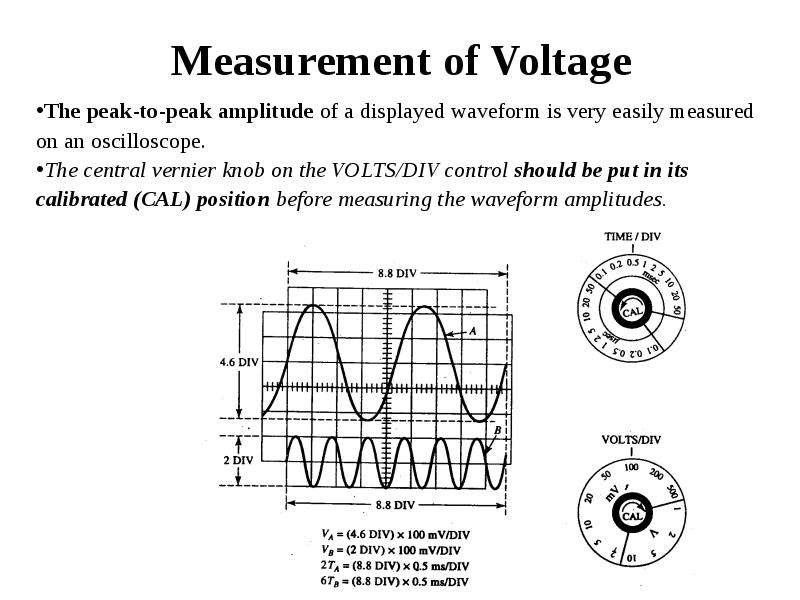
The peak-to-peak amplitude of a displayed waveform is very easily measured on an oscilloscope. 
The central vernier knob on the VOLTS/DIV control should be put in its calibrated (CAL) position before measuring the waveform amplitudes.
Описание слайда:
Measurement of Voltage The peak-to-peak amplitude of a displayed waveform is very easily measured on an oscilloscope. The central vernier knob on the VOLTS/DIV control should be put in its calibrated (CAL) position before measuring the waveform amplitudes.

Слайд 31


Measurement of Voltage
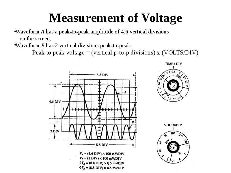
Waveform A has a peak-to-peak amplitude of 4.6 vertical divisions
    on the screen, 
Waveform B has 2 vertical divisions peak-to-peak. 
Peak to peak voltage = (vertical p-to-p divisions) x (VOLTS/DIV)
Описание слайда:
Measurement of Voltage Waveform A has a peak-to-peak amplitude of 4.6 vertical divisions on the screen, Waveform B has 2 vertical divisions peak-to-peak. Peak to peak voltage = (vertical p-to-p divisions) x (VOLTS/DIV)

Слайд 32


Frequency Determination
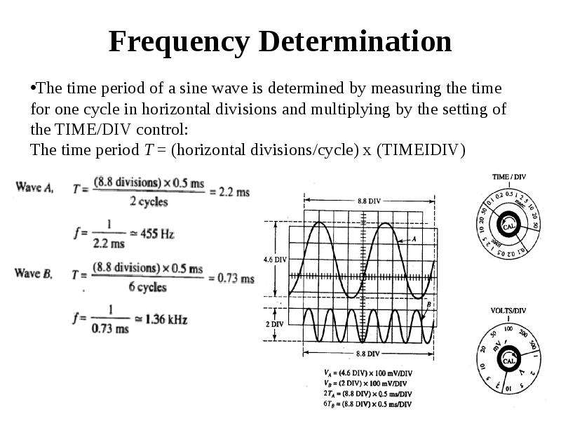
The time period of a sine wave is determined by measuring the time for one cycle in horizontal divisions and multiplying by the setting of the TIME/DIV control:
The time period T = (horizontal divisions/cycle) x (TIMEIDIV)
Описание слайда:
Frequency Determination The time period of a sine wave is determined by measuring the time for one cycle in horizontal divisions and multiplying by the setting of the TIME/DIV control: The time period T = (horizontal divisions/cycle) x (TIMEIDIV)

Слайд 33


Phase Measurement
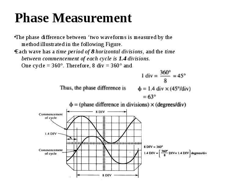
The phase difference between ‘two waveforms is measured by the
     method illustrated in the following Figure.
Each wave has a time period of 8 horizontal divisions, and the time
     between commencement of each cycle is 1.4 divisions. 
     One cycle = 360°. Therefore, 8 div = 360° and
Описание слайда:
Phase Measurement The phase difference between ‘two waveforms is measured by the method illustrated in the following Figure. Each wave has a time period of 8 horizontal divisions, and the time between commencement of each cycle is 1.4 divisions. One cycle = 360°. Therefore, 8 div = 360° and


Похожие презентации
Mypresentation.ru
Загрузить презентацию