🗊Презентация Invention

Категория: Технология
Нажмите для полного просмотра!
Invention, слайд №1Invention, слайд №2Invention, слайд №3Invention, слайд №4Invention, слайд №5Invention, слайд №6Invention, слайд №7Invention, слайд №8Invention, слайд №9Invention, слайд №10Invention, слайд №11Invention, слайд №12Invention, слайд №13Invention, слайд №14Invention, слайд №15Invention, слайд №16Invention, слайд №17Invention, слайд №18Invention, слайд №19Invention, слайд №20Invention, слайд №21Invention, слайд №22Invention, слайд №23Invention, слайд №24Invention, слайд №25Invention, слайд №26Invention, слайд №27Invention, слайд №28Invention, слайд №29Invention, слайд №30Invention, слайд №31Invention, слайд №32Invention, слайд №33Invention, слайд №34Invention, слайд №35Invention, слайд №36Invention, слайд №37Invention, слайд №38Invention, слайд №39Invention, слайд №40Invention, слайд №41Invention, слайд №42Invention, слайд №43Invention, слайд №44Invention, слайд №45Invention, слайд №46Invention, слайд №47Invention, слайд №48Invention, слайд №49Invention, слайд №50Invention, слайд №51

Содержание
Вы можете ознакомиться и скачать презентацию на тему Invention. Доклад-сообщение содержит 51 слайдов. Презентации для любого класса можно скачать бесплатно. Если материал и наш сайт презентаций Mypresentation Вам понравились – поделитесь им с друзьями с помощью социальных кнопок и добавьте в закладки в своем браузере.
Слайды и текст этой презентации


Слайд 1


Telephone
Mobile phone
Computer
Television
Internet
Electro-magnetic transmitters and receivers
Alexander Graham Bell
Bell's success
Variable resistance transmitters
Hertz
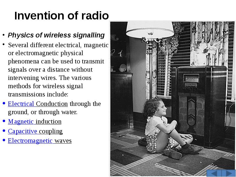
Invention of radio
Tesla
Bose
Braun
Early commercial exploitation
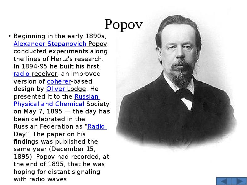
Popov
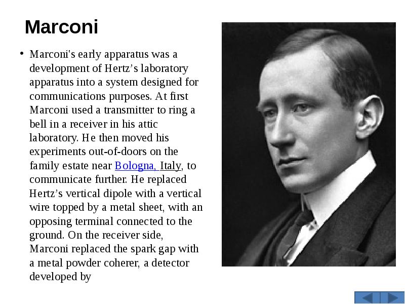
Marconi
Transatlantic transmissions
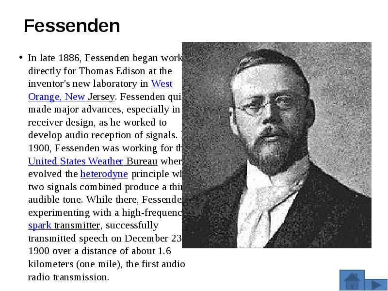
Fessenden
Описание слайда:
Telephone Mobile phone Computer Television Internet Electro-magnetic transmitters and receivers Alexander Graham Bell Bell's success Variable resistance transmitters Hertz Invention of radio Tesla Bose Braun Early commercial exploitation Popov Marconi Transatlantic transmissions Fessenden

Слайд 2


Invention of the telephone
Описание слайда:
Invention of the telephone

Слайд 3


The modern telephone is the culmination of work done by many individuals. Alexander Graham Bell was the first to patent the telephone, an "apparatus for transmitting vocal or other sounds telegraphically", after experimenting with many primitive sound transmitters and receivers. However, the history of the invention of the telephone is a confusing collection of claims and counterclaims, made no less confusing by the many lawsuits which attempted to resolve the patent claims of several individuals.
Описание слайда:
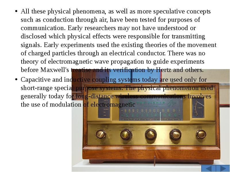
The modern telephone is the culmination of work done by many individuals. Alexander Graham Bell was the first to patent the telephone, an "apparatus for transmitting vocal or other sounds telegraphically", after experimenting with many primitive sound transmitters and receivers. However, the history of the invention of the telephone is a confusing collection of claims and counterclaims, made no less confusing by the many lawsuits which attempted to resolve the patent claims of several individuals. The modern telephone is the culmination of work done by many individuals. Alexander Graham Bell was the first to patent the telephone, an "apparatus for transmitting vocal or other sounds telegraphically", after experimenting with many primitive sound transmitters and receivers. However, the history of the invention of the telephone is a confusing collection of claims and counterclaims, made no less confusing by the many lawsuits which attempted to resolve the patent claims of several individuals.

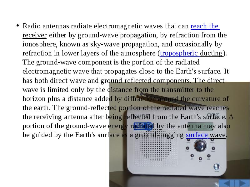
Слайд 4


Mobile phone 
A or mobile (also called cellphone and handphone)[1] is an electronic device used for mobile telecommunications (mobile telephone, text messaging or data transmission) over a cellular network of specialized base stations known as cell sites. Mobile phones differ from cordless telephones, which only offer telephone service within limited range, e.g. within a home or an office, through a fixed line and a base station owned by the subscriber and also from satellite phones and radio telephones. As opposed to a radio telephone, a cell phone offers full duplex communication, automates calling to and paging from a public land mobile network (PLMN), and handoff (handover) during a phone call when the user moves from one cell (base station coverage area) to another.
Описание слайда:
Mobile phone A or mobile (also called cellphone and handphone)[1] is an electronic device used for mobile telecommunications (mobile telephone, text messaging or data transmission) over a cellular network of specialized base stations known as cell sites. Mobile phones differ from cordless telephones, which only offer telephone service within limited range, e.g. within a home or an office, through a fixed line and a base station owned by the subscriber and also from satellite phones and radio telephones. As opposed to a radio telephone, a cell phone offers full duplex communication, automates calling to and paging from a public land mobile network (PLMN), and handoff (handover) during a phone call when the user moves from one cell (base station coverage area) to another.

Слайд 5


Most current cell phones connect to a cellular network consisting of switching points and base stations (cell sites) owned by a mobile network operator. In addition to the standard voice function, current mobile phones may support many additional services, and accessories, such as SMS for text messaging, email, packet switching for access to the Internet, gaming, Bluetooth, infrared, camera with video recorder and MMS for sending and receiving photos and video, MP3 player, radio and GPS. The concept of a handheld phone was Martin Cooper's brainchild, and with the help of his Motorola team, the first handset was born in 1973 weighing in at two kilos.[2]
The International Telecommunication Union estimated that mobile cellular subscriptions worldwide would reach approximately 4.6 billion by the end of 2009. Mobile phones have gained increased importance in the sector of Information and communication technologies for development in the 2000s and have effectively started to reach the bottom of the economic pyramid
Описание слайда:
Most current cell phones connect to a cellular network consisting of switching points and base stations (cell sites) owned by a mobile network operator. In addition to the standard voice function, current mobile phones may support many additional services, and accessories, such as SMS for text messaging, email, packet switching for access to the Internet, gaming, Bluetooth, infrared, camera with video recorder and MMS for sending and receiving photos and video, MP3 player, radio and GPS. The concept of a handheld phone was Martin Cooper's brainchild, and with the help of his Motorola team, the first handset was born in 1973 weighing in at two kilos.[2] Most current cell phones connect to a cellular network consisting of switching points and base stations (cell sites) owned by a mobile network operator. In addition to the standard voice function, current mobile phones may support many additional services, and accessories, such as SMS for text messaging, email, packet switching for access to the Internet, gaming, Bluetooth, infrared, camera with video recorder and MMS for sending and receiving photos and video, MP3 player, radio and GPS. The concept of a handheld phone was Martin Cooper's brainchild, and with the help of his Motorola team, the first handset was born in 1973 weighing in at two kilos.[2] The International Telecommunication Union estimated that mobile cellular subscriptions worldwide would reach approximately 4.6 billion by the end of 2009. Mobile phones have gained increased importance in the sector of Information and communication technologies for development in the 2000s and have effectively started to reach the bottom of the economic pyramid

Слайд 6


The invention of the computer

 There is not just one inventor of the computer, as the ideas of many scientists and engineers led to its invention. These ideas were developed in the 1930s and 1940s, mostly independently of each other, in Germany, Great Britain and the USA, and were turned into working machines. 
Описание слайда:
The invention of the computer  There is not just one inventor of the computer, as the ideas of many scientists and engineers led to its invention. These ideas were developed in the 1930s and 1940s, mostly independently of each other, in Germany, Great Britain and the USA, and were turned into working machines. 

Слайд 7


In Germany, Konrad Zuse hit upon the idea of building a program-controlled calculating machine when he had to deal with extensive calculations in statics. In 1935, he began to design a program-controlled calculating machine in his parents' home in Berlin. It was based on the binary system and used punched tape for the program input. The Z1, which was built between 1936 and 1938, was a purely mechanical machine which was not fully operational. In 1940, Zuse began to build a successor to the Z1 based on relay technology. In May 1941, he finished the Z3 - worldwide the first freely programmable program-controlled automatic calculator that was operational. Several similar developments were in progress in the USA at the same time. In 1939, IBM started to build a program-controlled relay calculator on the basis of a concept that Howard H. Aiken had put forward in 1937. This machine - the IBM Automatic Sequence Controlled Calculator (Mark I) - was used on production work from 1944.
Описание слайда:
In Germany, Konrad Zuse hit upon the idea of building a program-controlled calculating machine when he had to deal with extensive calculations in statics. In 1935, he began to design a program-controlled calculating machine in his parents' home in Berlin. It was based on the binary system and used punched tape for the program input. The Z1, which was built between 1936 and 1938, was a purely mechanical machine which was not fully operational. In 1940, Zuse began to build a successor to the Z1 based on relay technology. In May 1941, he finished the Z3 - worldwide the first freely programmable program-controlled automatic calculator that was operational. Several similar developments were in progress in the USA at the same time. In 1939, IBM started to build a program-controlled relay calculator on the basis of a concept that Howard H. Aiken had put forward in 1937. This machine - the IBM Automatic Sequence Controlled Calculator (Mark I) - was used on production work from 1944. In Germany, Konrad Zuse hit upon the idea of building a program-controlled calculating machine when he had to deal with extensive calculations in statics. In 1935, he began to design a program-controlled calculating machine in his parents' home in Berlin. It was based on the binary system and used punched tape for the program input. The Z1, which was built between 1936 and 1938, was a purely mechanical machine which was not fully operational. In 1940, Zuse began to build a successor to the Z1 based on relay technology. In May 1941, he finished the Z3 - worldwide the first freely programmable program-controlled automatic calculator that was operational. Several similar developments were in progress in the USA at the same time. In 1939, IBM started to build a program-controlled relay calculator on the basis of a concept that Howard H. Aiken had put forward in 1937. This machine - the IBM Automatic Sequence Controlled Calculator (Mark I) - was used on production work from 1944.

Слайд 8


However, it was not Aiken's and Stibitz's relay calculators that were decisive for the development of the universal computer but the ENIAC, which was developed at the Moore School of Electrical Engineering at the University of Pennsylvania. Extensive ballistic computations were carried out there for the U.S. Army during World War II with the aid of a copy of the analog Differential Analyzer, which had been designed by Vannevar Bush, and more than a hundred women working on mechanical desk calculators. Nevertheless, capacity was barely sufficient to compute the artillery firing tables that were needed. 
However, it was not Aiken's and Stibitz's relay calculators that were decisive for the development of the universal computer but the ENIAC, which was developed at the Moore School of Electrical Engineering at the University of Pennsylvania. Extensive ballistic computations were carried out there for the U.S. Army during World War II with the aid of a copy of the analog Differential Analyzer, which had been designed by Vannevar Bush, and more than a hundred women working on mechanical desk calculators. Nevertheless, capacity was barely sufficient to compute the artillery firing tables that were needed.
Описание слайда:
However, it was not Aiken's and Stibitz's relay calculators that were decisive for the development of the universal computer but the ENIAC, which was developed at the Moore School of Electrical Engineering at the University of Pennsylvania. Extensive ballistic computations were carried out there for the U.S. Army during World War II with the aid of a copy of the analog Differential Analyzer, which had been designed by Vannevar Bush, and more than a hundred women working on mechanical desk calculators. Nevertheless, capacity was barely sufficient to compute the artillery firing tables that were needed. However, it was not Aiken's and Stibitz's relay calculators that were decisive for the development of the universal computer but the ENIAC, which was developed at the Moore School of Electrical Engineering at the University of Pennsylvania. Extensive ballistic computations were carried out there for the U.S. Army during World War II with the aid of a copy of the analog Differential Analyzer, which had been designed by Vannevar Bush, and more than a hundred women working on mechanical desk calculators. Nevertheless, capacity was barely sufficient to compute the artillery firing tables that were needed.

Слайд 9


John von Neumann, an influential mathematician, turned his attention to the ENIAC in the summer of 1944. While this computer was being built, von Neumann and the ENIAC team drew up a plan for a successor to the ENIAC. The biggest problem with the ENIAC was that its memory was too small. Eckert suggested a mercury delay-line memory which would increase memory capacity by a factor of 100 compared with the electronic memory used in the ENIAC.
An equally big problem was programming the ENIAC, which could take hours or even days.
 In meetings with von Neumann, the idea of a stored-program, universal machine evolved. Memory was to be used to store the program in addition to data. This would enable the machine to execute conditional branches and change the flow of the program. The concept of a computer in the modern sense of the word was born.
Описание слайда:
John von Neumann, an influential mathematician, turned his attention to the ENIAC in the summer of 1944. While this computer was being built, von Neumann and the ENIAC team drew up a plan for a successor to the ENIAC. The biggest problem with the ENIAC was that its memory was too small. Eckert suggested a mercury delay-line memory which would increase memory capacity by a factor of 100 compared with the electronic memory used in the ENIAC. John von Neumann, an influential mathematician, turned his attention to the ENIAC in the summer of 1944. While this computer was being built, von Neumann and the ENIAC team drew up a plan for a successor to the ENIAC. The biggest problem with the ENIAC was that its memory was too small. Eckert suggested a mercury delay-line memory which would increase memory capacity by a factor of 100 compared with the electronic memory used in the ENIAC. An equally big problem was programming the ENIAC, which could take hours or even days.  In meetings with von Neumann, the idea of a stored-program, universal machine evolved. Memory was to be used to store the program in addition to data. This would enable the machine to execute conditional branches and change the flow of the program. The concept of a computer in the modern sense of the word was born.

Слайд 10


In spring 1944, von Neumann wrote his "First Draft of a Report on the EDVAC" (Electronic Discrete Variable Computer) which described the stored-program, universal computer. The logical structure that was presented in this draft report is now referred to as the von Neumann architecture. This EDVAC report was originally intended for internal use only but it became the "bible" for computer pioneers throughout the world in the 1940s and 1950s. 
Описание слайда:
In spring 1944, von Neumann wrote his "First Draft of a Report on the EDVAC" (Electronic Discrete Variable Computer) which described the stored-program, universal computer. The logical structure that was presented in this draft report is now referred to as the von Neumann architecture. This EDVAC report was originally intended for internal use only but it became the "bible" for computer pioneers throughout the world in the 1940s and 1950s.  In spring 1944, von Neumann wrote his "First Draft of a Report on the EDVAC" (Electronic Discrete Variable Computer) which described the stored-program, universal computer. The logical structure that was presented in this draft report is now referred to as the von Neumann architecture. This EDVAC report was originally intended for internal use only but it became the "bible" for computer pioneers throughout the world in the 1940s and 1950s. 

Слайд 11


Television
In 1921 the 14-year-old Mormon had an idea while working on his father's Idaho farm. Mowing hay in rows, Philo realized an electron beam could scan a picture in horizontal lines, reproducing the image almost instantaneously. This would prove to be a critical breakthrough in Philo Farnsworth's invention of the television in 1927. Earlier TV devices had been based on an 1884 invention called the scanning disk, patented by Paul Nipkow. Riddled with holes, the large disk spun in front of an object while a photoelectric cell recorded changes in light. Depending on the electricity transmitted by the photoelectric cell, an array of light bulbs would glow or remain dark. Though Nipkow's mechanical system could not scan and deliver a clear, live-action image, most would-be TV inventors still hoped to perfect it.
Описание слайда:
Television In 1921 the 14-year-old Mormon had an idea while working on his father's Idaho farm. Mowing hay in rows, Philo realized an electron beam could scan a picture in horizontal lines, reproducing the image almost instantaneously. This would prove to be a critical breakthrough in Philo Farnsworth's invention of the television in 1927. Earlier TV devices had been based on an 1884 invention called the scanning disk, patented by Paul Nipkow. Riddled with holes, the large disk spun in front of an object while a photoelectric cell recorded changes in light. Depending on the electricity transmitted by the photoelectric cell, an array of light bulbs would glow or remain dark. Though Nipkow's mechanical system could not scan and deliver a clear, live-action image, most would-be TV inventors still hoped to perfect it.

Слайд 12


Not Philo Farnsworth. In 1921 the 14-year-old Mormon had an idea while working on his father's Idaho farm. Mowing hay in rows, Philo realized an electron beam could scan a picture in horizontal lines, reproducing the image almost instantaneously. It would prove to be a critical breakthrough. 
But young Philo was not alone. At the same time, Russian immigrant Vladimir Zworykin had also designed a camera that focused an image through a lens onto an array of photoelectric cells coating the end of a tube. The electrical image formed by the cells would be scanned line-by-line by an electron beam and transmitted to a cathode-ray tube. 
Rather than an electron beam, Farnsworth's image dissector device used an "anode finger" -- a pencil-sized tube with a small aperture at the top -- to scan the picture. Magnetic coils sprayed the electrons emitted from the electrical image left to right and line by line onto the aperture, where they became electric current. Both Zworykin's and Philo's devices then transmitted the current to a cathode-ray tube, which recreated the image by scanning it onto a fluorescent surface.
Описание слайда:
Not Philo Farnsworth. In 1921 the 14-year-old Mormon had an idea while working on his father's Idaho farm. Mowing hay in rows, Philo realized an electron beam could scan a picture in horizontal lines, reproducing the image almost instantaneously. It would prove to be a critical breakthrough. Not Philo Farnsworth. In 1921 the 14-year-old Mormon had an idea while working on his father's Idaho farm. Mowing hay in rows, Philo realized an electron beam could scan a picture in horizontal lines, reproducing the image almost instantaneously. It would prove to be a critical breakthrough. But young Philo was not alone. At the same time, Russian immigrant Vladimir Zworykin had also designed a camera that focused an image through a lens onto an array of photoelectric cells coating the end of a tube. The electrical image formed by the cells would be scanned line-by-line by an electron beam and transmitted to a cathode-ray tube. Rather than an electron beam, Farnsworth's image dissector device used an "anode finger" -- a pencil-sized tube with a small aperture at the top -- to scan the picture. Magnetic coils sprayed the electrons emitted from the electrical image left to right and line by line onto the aperture, where they became electric current. Both Zworykin's and Philo's devices then transmitted the current to a cathode-ray tube, which recreated the image by scanning it onto a fluorescent surface.

Слайд 13


Farnsworth applied for a patent for his image dissector in 1927. The development of the television system was plagued by lack of money and by challenges to Farnsworth's patent from the giant Radio Corporation of America (RCA). In 1934, the British communications company British Gaumont bought a license from Farnsworth to make systems based on his designs. In 1939, the American company RCA did the same. Both companies had been developing television systems of their own and recognized Farnsworth as a competitor. World War II interrupted the development of television. When television broadcasts became a regular occurrence after the war, Farnsworth was not involved. Instead, he devoted his time to trying to perfect the devices he had designed.
Описание слайда:
Farnsworth applied for a patent for his image dissector in 1927. The development of the television system was plagued by lack of money and by challenges to Farnsworth's patent from the giant Radio Corporation of America (RCA). In 1934, the British communications company British Gaumont bought a license from Farnsworth to make systems based on his designs. In 1939, the American company RCA did the same. Both companies had been developing television systems of their own and recognized Farnsworth as a competitor. World War II interrupted the development of television. When television broadcasts became a regular occurrence after the war, Farnsworth was not involved. Instead, he devoted his time to trying to perfect the devices he had designed. Farnsworth applied for a patent for his image dissector in 1927. The development of the television system was plagued by lack of money and by challenges to Farnsworth's patent from the giant Radio Corporation of America (RCA). In 1934, the British communications company British Gaumont bought a license from Farnsworth to make systems based on his designs. In 1939, the American company RCA did the same. Both companies had been developing television systems of their own and recognized Farnsworth as a competitor. World War II interrupted the development of television. When television broadcasts became a regular occurrence after the war, Farnsworth was not involved. Instead, he devoted his time to trying to perfect the devices he had designed.

Слайд 14


David Sarnoff, vice president of the powerful Radio Corporation of America, later hired Zworykin to ensure that RCA would control television technology. Zworykin and Sarnoff visited Farnsworth's cluttered laboratory, but the Mormon inventor's business manager scoffed at selling the company -- and Farnsworth's services -- to RCA for a piddling $100,000. So Sarnoff haughtily downplayed the importance of Philo's innovations, saying, "There's nothing here we'll need." 
In 1934 RCA demonstrated its "iconoscope," a camera tube very similar to Farnsworth's image dissector. RCA claimed it was based on a device Zworykin tried to patent in 1923 -- even though the Russian had used Nipkow's old spinning disk design up until the time he visited Philo's lab. 
The patent wars had truly begun -- and Phil, as the grown-up Farnsworth preferred to be called, was in a bind. He could not license his inventions while the matter was in court, and he wrestled with his backers over control and direction of his own company. The men in Farnsworth's loyal "lab gang" were fired and rehired several times during his financial ups and downs, but retained confidence in Phil. When Farnsworth's financiers refused his request for a broadcasting studio, the inventor and a partner built a studio on their own.
Описание слайда:
David Sarnoff, vice president of the powerful Radio Corporation of America, later hired Zworykin to ensure that RCA would control television technology. Zworykin and Sarnoff visited Farnsworth's cluttered laboratory, but the Mormon inventor's business manager scoffed at selling the company -- and Farnsworth's services -- to RCA for a piddling $100,000. So Sarnoff haughtily downplayed the importance of Philo's innovations, saying, "There's nothing here we'll need." David Sarnoff, vice president of the powerful Radio Corporation of America, later hired Zworykin to ensure that RCA would control television technology. Zworykin and Sarnoff visited Farnsworth's cluttered laboratory, but the Mormon inventor's business manager scoffed at selling the company -- and Farnsworth's services -- to RCA for a piddling $100,000. So Sarnoff haughtily downplayed the importance of Philo's innovations, saying, "There's nothing here we'll need." In 1934 RCA demonstrated its "iconoscope," a camera tube very similar to Farnsworth's image dissector. RCA claimed it was based on a device Zworykin tried to patent in 1923 -- even though the Russian had used Nipkow's old spinning disk design up until the time he visited Philo's lab. The patent wars had truly begun -- and Phil, as the grown-up Farnsworth preferred to be called, was in a bind. He could not license his inventions while the matter was in court, and he wrestled with his backers over control and direction of his own company. The men in Farnsworth's loyal "lab gang" were fired and rehired several times during his financial ups and downs, but retained confidence in Phil. When Farnsworth's financiers refused his request for a broadcasting studio, the inventor and a partner built a studio on their own.

Слайд 15


Meanwhile back at RCA, Sarnoff had spent more than $10 million on a major TV R & D effort. At the 1939 New York World's Fair, Sarnoff announced the launch of commercial television -- though RCA's camera was inadequate, and the corporation didn't own a single TV patent. Later that same year, the company was compelled to pay patent royalties to Farnsworth Radio and Television. 
By the time World War II began, Farnsworth realized that commercial television's future was in the hands of businessmen -- not a lone inventor toiling in his lab. With his patents about to expire, Phil grew depressed, drunk and addicted to painkillers. In 1949 he reluctantly agreed to sell off Farnsworth Radio and Television. 
Philo T. Farnsworth was always an outsider, a bright star blazing in the dawn of a new electronic age. His romance with the electron was a private affair, a celebration of the spirit of the lone inventor.
Описание слайда:
Meanwhile back at RCA, Sarnoff had spent more than $10 million on a major TV R & D effort. At the 1939 New York World's Fair, Sarnoff announced the launch of commercial television -- though RCA's camera was inadequate, and the corporation didn't own a single TV patent. Later that same year, the company was compelled to pay patent royalties to Farnsworth Radio and Television. By the time World War II began, Farnsworth realized that commercial television's future was in the hands of businessmen -- not a lone inventor toiling in his lab. With his patents about to expire, Phil grew depressed, drunk and addicted to painkillers. In 1949 he reluctantly agreed to sell off Farnsworth Radio and Television. Philo T. Farnsworth was always an outsider, a bright star blazing in the dawn of a new electronic age. His romance with the electron was a private affair, a celebration of the spirit of the lone inventor.

Слайд 16


Internet
The Internet is a worldwide network of thousands of computers and computer networks. It is a public, voluntary, and cooperative effort between the connected institutions and is not owned or operated by any single organization.  The Internet and Transmission Control Protocols were initially developed in 1973 by American computer scientist Vinton Cerf as part of a project sponsored by the United States Department of Defense Advanced Research Projects Agency (ARPA) and directed by American engineer Robert Kahn.
Описание слайда:
Internet The Internet is a worldwide network of thousands of computers and computer networks. It is a public, voluntary, and cooperative effort between the connected institutions and is not owned or operated by any single organization.  The Internet and Transmission Control Protocols were initially developed in 1973 by American computer scientist Vinton Cerf as part of a project sponsored by the United States Department of Defense Advanced Research Projects Agency (ARPA) and directed by American engineer Robert Kahn.

Слайд 17


The Internet began as a computer network of ARPA (ARPAnet) that linked computer networks at several universities and research laboratories in the United States. The World Wide Web was developed in 1989 by English computer scientist Timothy Berners-Lee for the European Organization for Nuclear Research (CERN).
"The design of the Internet was done in 1973 and published in 1974. There ensued about 10 years of hard work, resulting in the roll out of Internet in 1983. Prior to that, a number of demonstrations were made of the technology - such as the first three-network interconnection demonstrated in November 1977 linking SATNET, PRNET and ARPANET in a path leading from Menlo Park, CA to University College London and back to USC/ISI in Marina del Rey, CA.“ Vinton Cerf explains the timing:
Internet, interconnection of computer networks that enables connected machines to communicate directly. The term popularly refers to a particular global interconnection of government, education, and business computer networks that is available to the public. There are also smaller internets, usually for the private use of a single organization, called intranets.
Описание слайда:
The Internet began as a computer network of ARPA (ARPAnet) that linked computer networks at several universities and research laboratories in the United States. The World Wide Web was developed in 1989 by English computer scientist Timothy Berners-Lee for the European Organization for Nuclear Research (CERN). The Internet began as a computer network of ARPA (ARPAnet) that linked computer networks at several universities and research laboratories in the United States. The World Wide Web was developed in 1989 by English computer scientist Timothy Berners-Lee for the European Organization for Nuclear Research (CERN). "The design of the Internet was done in 1973 and published in 1974. There ensued about 10 years of hard work, resulting in the roll out of Internet in 1983. Prior to that, a number of demonstrations were made of the technology - such as the first three-network interconnection demonstrated in November 1977 linking SATNET, PRNET and ARPANET in a path leading from Menlo Park, CA to University College London and back to USC/ISI in Marina del Rey, CA.“ Vinton Cerf explains the timing: Internet, interconnection of computer networks that enables connected machines to communicate directly. The term popularly refers to a particular global interconnection of government, education, and business computer networks that is available to the public. There are also smaller internets, usually for the private use of a single organization, called intranets.

Слайд 18


Internet technology is a primitive precursor of the Information Superhighway, a theoretical goal of computer communications to provide schools, libraries, businesses, and homes universal access to quality information that will educate, inform, and entertain. In early 1996, the Internet interconnected more than 25 million computers in over 180 countries and continues to grow at a dramatic rate.
How Internets Work
Internets are formed by connecting local networks through special computers in each network known as gateways. Gateway interconnections are made through various communication paths, including telephone lines, optical fibers, and radio links. Additional networks can be added by linking to new gateways. Information to be delivered to a remote machine is tagged with the computerized address of that particular machine.
Описание слайда:
Internet technology is a primitive precursor of the Information Superhighway, a theoretical goal of computer communications to provide schools, libraries, businesses, and homes universal access to quality information that will educate, inform, and entertain. In early 1996, the Internet interconnected more than 25 million computers in over 180 countries and continues to grow at a dramatic rate. Internet technology is a primitive precursor of the Information Superhighway, a theoretical goal of computer communications to provide schools, libraries, businesses, and homes universal access to quality information that will educate, inform, and entertain. In early 1996, the Internet interconnected more than 25 million computers in over 180 countries and continues to grow at a dramatic rate. How Internets Work Internets are formed by connecting local networks through special computers in each network known as gateways. Gateway interconnections are made through various communication paths, including telephone lines, optical fibers, and radio links. Additional networks can be added by linking to new gateways. Information to be delivered to a remote machine is tagged with the computerized address of that particular machine.

Слайд 19


Invention, слайд №19
Описание слайда:

Слайд 20


Different types of addressing formats are used by the various services provided by internets (see Internet address). One format is known as dotted decimal, for example: 123.45.67.89. Another format describes the name of the destination computer and other routing information, such as "machine.dept.univ.edu." The suffix at the end of the internet address designates the type of organization that owns the particular computer network, for example, educational institutions (.edu), military locations (.mil), government offices (.gov), and non-profit organizations (.org). Networks outside the United States use suffixes that indicate the country, for example (.ca) for Canada.
Once addressed, the information leaves its home network through a gateway. It is routed from gateway to gateway until it reaches the local network containing the destination machine. Internets have no central control, that is, no single computer directs the flow of information. This differentiates internets from other types of online computer services, such as CompuServe, America Online, and the Microsoft Network.
Описание слайда:
Different types of addressing formats are used by the various services provided by internets (see Internet address). One format is known as dotted decimal, for example: 123.45.67.89. Another format describes the name of the destination computer and other routing information, such as "machine.dept.univ.edu." The suffix at the end of the internet address designates the type of organization that owns the particular computer network, for example, educational institutions (.edu), military locations (.mil), government offices (.gov), and non-profit organizations (.org). Networks outside the United States use suffixes that indicate the country, for example (.ca) for Canada. Different types of addressing formats are used by the various services provided by internets (see Internet address). One format is known as dotted decimal, for example: 123.45.67.89. Another format describes the name of the destination computer and other routing information, such as "machine.dept.univ.edu." The suffix at the end of the internet address designates the type of organization that owns the particular computer network, for example, educational institutions (.edu), military locations (.mil), government offices (.gov), and non-profit organizations (.org). Networks outside the United States use suffixes that indicate the country, for example (.ca) for Canada. Once addressed, the information leaves its home network through a gateway. It is routed from gateway to gateway until it reaches the local network containing the destination machine. Internets have no central control, that is, no single computer directs the flow of information. This differentiates internets from other types of online computer services, such as CompuServe, America Online, and the Microsoft Network.

Слайд 21


The Internet Protocol
The Internet Protocol is the basic software used to control an internet. This protocol specifies how gateway machines route information from the sending computer to the recipient computer. Another protocol, Transmission Control Protocol, checks whether the information has arrived at the destination computer and, if not, causes the information to be resent. 
Even though computer interaction is in its infancy, it has dramatically changed our world, bridging the barriers of time and distance, allowing people to share information and work together. Evolution toward the Information Superhighway will continue at an accelerating rate. Available content will grow rapidly, making it easier to find any information on the Internet. New applications will provide secure business transactions and new opportunities for commerce. New technologies will increase the speed of information transfer, allowing direct transfer of entertainment-on-demand. Broadcast television may be replaced by unicast, in which each home receives a signal especially tailored for what its residents want to see when they want to see it.
Описание слайда:
The Internet Protocol The Internet Protocol is the basic software used to control an internet. This protocol specifies how gateway machines route information from the sending computer to the recipient computer. Another protocol, Transmission Control Protocol, checks whether the information has arrived at the destination computer and, if not, causes the information to be resent. The Internet Protocol The Internet Protocol is the basic software used to control an internet. This protocol specifies how gateway machines route information from the sending computer to the recipient computer. Another protocol, Transmission Control Protocol, checks whether the information has arrived at the destination computer and, if not, causes the information to be resent. Even though computer interaction is in its infancy, it has dramatically changed our world, bridging the barriers of time and distance, allowing people to share information and work together. Evolution toward the Information Superhighway will continue at an accelerating rate. Available content will grow rapidly, making it easier to find any information on the Internet. New applications will provide secure business transactions and new opportunities for commerce. New technologies will increase the speed of information transfer, allowing direct transfer of entertainment-on-demand. Broadcast television may be replaced by unicast, in which each home receives a signal especially tailored for what its residents want to see when they want to see it.

Слайд 22


Invention, слайд №22
Описание слайда:

Слайд 23


Electro-magnetic transmitters and receivers
Elisha Gray, of Highland Park, Illinois (near Chicago) also devised a tone telegraph of this kind about the same time as La Cour. In Gray's tone telegraph, several vibrating steel reeds tuned to different frequencies interrupted the current, which at the other end of the line passed through electromagnets and vibrated matching tuned steel reeds near the electromagnet poles. Gray's 'harmonic telegraph,' with vibrating reeds, was used by the Western Union Telegraph Company. Since more than one set of vibration frequencies — that is to say, more than one musical tone — can be sent over the same wire simultaneously, the harmonic telegraph can be utilised as a 'multiplex' or many-ply telegraph, conveying several messages through the same wire at the same time. Each message can either be read by an operator by the sound, or from different tones read by different operators, or a permanent record can be made by the marks drawn on a ribbon of travelling paper by a Morse recorder. On 27 July 1875, Gray was granted U.S. patent 166,096 for "Electric Telegraph for Transmitting Musical Tones" (the harmonic telegraph).
Описание слайда:
Electro-magnetic transmitters and receivers Elisha Gray, of Highland Park, Illinois (near Chicago) also devised a tone telegraph of this kind about the same time as La Cour. In Gray's tone telegraph, several vibrating steel reeds tuned to different frequencies interrupted the current, which at the other end of the line passed through electromagnets and vibrated matching tuned steel reeds near the electromagnet poles. Gray's 'harmonic telegraph,' with vibrating reeds, was used by the Western Union Telegraph Company. Since more than one set of vibration frequencies — that is to say, more than one musical tone — can be sent over the same wire simultaneously, the harmonic telegraph can be utilised as a 'multiplex' or many-ply telegraph, conveying several messages through the same wire at the same time. Each message can either be read by an operator by the sound, or from different tones read by different operators, or a permanent record can be made by the marks drawn on a ribbon of travelling paper by a Morse recorder. On 27 July 1875, Gray was granted U.S. patent 166,096 for "Electric Telegraph for Transmitting Musical Tones" (the harmonic telegraph).

Слайд 24


On 14 February 1876, Gray filed a patent caveat for a telephone on the very same day in 1876 as did Bell's lawyer. The water transmitter described in Gray's caveat was strikingly similar to the experimental telephone transmitter tested by Bell on March 10, 1876, a fact which raised questions about whether Bell (who knew of Gray) was inspired by Gray's design or vice versa. Although Bell did not use Gray's water transmitter in later telephones, evidence suggests that Bell's lawyers may have obtained an unfair advantage over Gray.
Описание слайда:
On 14 February 1876, Gray filed a patent caveat for a telephone on the very same day in 1876 as did Bell's lawyer. The water transmitter described in Gray's caveat was strikingly similar to the experimental telephone transmitter tested by Bell on March 10, 1876, a fact which raised questions about whether Bell (who knew of Gray) was inspired by Gray's design or vice versa. Although Bell did not use Gray's water transmitter in later telephones, evidence suggests that Bell's lawyers may have obtained an unfair advantage over Gray. On 14 February 1876, Gray filed a patent caveat for a telephone on the very same day in 1876 as did Bell's lawyer. The water transmitter described in Gray's caveat was strikingly similar to the experimental telephone transmitter tested by Bell on March 10, 1876, a fact which raised questions about whether Bell (who knew of Gray) was inspired by Gray's design or vice versa. Although Bell did not use Gray's water transmitter in later telephones, evidence suggests that Bell's lawyers may have obtained an unfair advantage over Gray.

Слайд 25


Alexander Graham Bell
Alexander Graham Bell of Scotland is commonly credited as the inventor of the first practical telephone. The classic story of his crying out "Watson, come here! I want to see you!" is a well known part of American history[11]. But Alexander Graham Bell was also an astute and articulate business man with influential and wealthy friends.
Описание слайда:
Alexander Graham Bell Alexander Graham Bell of Scotland is commonly credited as the inventor of the first practical telephone. The classic story of his crying out "Watson, come here! I want to see you!" is a well known part of American history[11]. But Alexander Graham Bell was also an astute and articulate business man with influential and wealthy friends.

Слайд 26


As Professor of Vocal Physiology at Boston University, Bell was engaged in training teachers in the art of instructing deaf mutes how to speak, and experimented with the Leon Scott phonautograph in recording the vibrations of speech. This apparatus consists essentially of a thin membrane vibrated by the voice and carrying a light-weight stylus, which traces an undulatory line on a plate of smoked glass. The line is a graphic representation of the vibrations of the membrane and the waves of sound in the air.[12]
This background prepared Bell for work with spoken sound waves and electricity. He began his experiments in 1873-1874 with a harmonic telegraph, following the examples of Bourseul, Reis, Meucci, and Gray. Bell's designs employed various on-off-on-off make-break current-interrupters driven by vibrating steel reeds which sent interrupted current to a distant receiver electro-magnet that caused a second steel reed or tuning fork to vibrate.
Описание слайда:
As Professor of Vocal Physiology at Boston University, Bell was engaged in training teachers in the art of instructing deaf mutes how to speak, and experimented with the Leon Scott phonautograph in recording the vibrations of speech. This apparatus consists essentially of a thin membrane vibrated by the voice and carrying a light-weight stylus, which traces an undulatory line on a plate of smoked glass. The line is a graphic representation of the vibrations of the membrane and the waves of sound in the air.[12] As Professor of Vocal Physiology at Boston University, Bell was engaged in training teachers in the art of instructing deaf mutes how to speak, and experimented with the Leon Scott phonautograph in recording the vibrations of speech. This apparatus consists essentially of a thin membrane vibrated by the voice and carrying a light-weight stylus, which traces an undulatory line on a plate of smoked glass. The line is a graphic representation of the vibrations of the membrane and the waves of sound in the air.[12] This background prepared Bell for work with spoken sound waves and electricity. He began his experiments in 1873-1874 with a harmonic telegraph, following the examples of Bourseul, Reis, Meucci, and Gray. Bell's designs employed various on-off-on-off make-break current-interrupters driven by vibrating steel reeds which sent interrupted current to a distant receiver electro-magnet that caused a second steel reed or tuning fork to vibrate.

Слайд 27


During a June 2, 1875 experiment by Bell and his assistant Watson, a receiver reed failed to respond to the intermittent current supplied by an electric battery. Bell told Watson, who was at the other end of the line, to pluck the reed, thinking it had stuck to the pole of the magnet. Mr. Watson complied, and to his astonishment Bell heard a reed at his end of the line vibrate and emit the same timbre of a plucked reed, although there was no interrupted on-off-on-off current from a transmitter to make it vibrate.[14] A few more experiments soon showed that his receiver reed had been set in vibration by the magneto-electric currents induced in the line by the motion of the distant receiver reed in the neighbourhood of its magnet. The battery current was not causing the vibration but was needed only to supply the magnetic field in which the reeds vibrated. Moreover, when Bell heard the rich overtones of the plucked reed, it occurred to him that since the circuit was never broken, all the complex vibrations of speech might be converted into undulating (alternating) currents, which in turn would reproduce the complex timbre, amplitude, and frequencies of speech at a distance.
Описание слайда:
During a June 2, 1875 experiment by Bell and his assistant Watson, a receiver reed failed to respond to the intermittent current supplied by an electric battery. Bell told Watson, who was at the other end of the line, to pluck the reed, thinking it had stuck to the pole of the magnet. Mr. Watson complied, and to his astonishment Bell heard a reed at his end of the line vibrate and emit the same timbre of a plucked reed, although there was no interrupted on-off-on-off current from a transmitter to make it vibrate.[14] A few more experiments soon showed that his receiver reed had been set in vibration by the magneto-electric currents induced in the line by the motion of the distant receiver reed in the neighbourhood of its magnet. The battery current was not causing the vibration but was needed only to supply the magnetic field in which the reeds vibrated. Moreover, when Bell heard the rich overtones of the plucked reed, it occurred to him that since the circuit was never broken, all the complex vibrations of speech might be converted into undulating (alternating) currents, which in turn would reproduce the complex timbre, amplitude, and frequencies of speech at a distance. During a June 2, 1875 experiment by Bell and his assistant Watson, a receiver reed failed to respond to the intermittent current supplied by an electric battery. Bell told Watson, who was at the other end of the line, to pluck the reed, thinking it had stuck to the pole of the magnet. Mr. Watson complied, and to his astonishment Bell heard a reed at his end of the line vibrate and emit the same timbre of a plucked reed, although there was no interrupted on-off-on-off current from a transmitter to make it vibrate.[14] A few more experiments soon showed that his receiver reed had been set in vibration by the magneto-electric currents induced in the line by the motion of the distant receiver reed in the neighbourhood of its magnet. The battery current was not causing the vibration but was needed only to supply the magnetic field in which the reeds vibrated. Moreover, when Bell heard the rich overtones of the plucked reed, it occurred to him that since the circuit was never broken, all the complex vibrations of speech might be converted into undulating (alternating) currents, which in turn would reproduce the complex timbre, amplitude, and frequencies of speech at a distance.

Слайд 28


After Bell and Watson discovered on June 2, 1875 that movements of the reed alone in a magnetic field could reproduce the frequencies and timbre of spoken sound waves, Bell reasoned by analogy with the mechanical phonautograph that a skin diaphragm would reproduce sounds like the human ear when connected to a steel or iron reed or hinged armature. On July 1, 1875, he instructed Watson to build a receiver consisting of a stretched diaphragm or drum of goldbeater's skin with an armature of magnetized iron attached to its middle, and free to vibrate in front of the pole of an electromagnet in circuit with the line. A second membrane-device was built for use as a transmitter.[15] This was the "gallows" phone. A few days later they were tried together, one at each end of the line, which ran from a room in the inventor's house in Boston to the cellar underneath. Bell, in the work room, held one instrument in his hands, while Watson in the cellar listened at the other. 
After Bell and Watson discovered on June 2, 1875 that movements of the reed alone in a magnetic field could reproduce the frequencies and timbre of spoken sound waves, Bell reasoned by analogy with the mechanical phonautograph that a skin diaphragm would reproduce sounds like the human ear when connected to a steel or iron reed or hinged armature. On July 1, 1875, he instructed Watson to build a receiver consisting of a stretched diaphragm or drum of goldbeater's skin with an armature of magnetized iron attached to its middle, and free to vibrate in front of the pole of an electromagnet in circuit with the line. A second membrane-device was built for use as a transmitter.[15] This was the "gallows" phone. A few days later they were tried together, one at each end of the line, which ran from a room in the inventor's house in Boston to the cellar underneath. Bell, in the work room, held one instrument in his hands, while Watson in the cellar listened at the other.
Описание слайда:
After Bell and Watson discovered on June 2, 1875 that movements of the reed alone in a magnetic field could reproduce the frequencies and timbre of spoken sound waves, Bell reasoned by analogy with the mechanical phonautograph that a skin diaphragm would reproduce sounds like the human ear when connected to a steel or iron reed or hinged armature. On July 1, 1875, he instructed Watson to build a receiver consisting of a stretched diaphragm or drum of goldbeater's skin with an armature of magnetized iron attached to its middle, and free to vibrate in front of the pole of an electromagnet in circuit with the line. A second membrane-device was built for use as a transmitter.[15] This was the "gallows" phone. A few days later they were tried together, one at each end of the line, which ran from a room in the inventor's house in Boston to the cellar underneath. Bell, in the work room, held one instrument in his hands, while Watson in the cellar listened at the other. After Bell and Watson discovered on June 2, 1875 that movements of the reed alone in a magnetic field could reproduce the frequencies and timbre of spoken sound waves, Bell reasoned by analogy with the mechanical phonautograph that a skin diaphragm would reproduce sounds like the human ear when connected to a steel or iron reed or hinged armature. On July 1, 1875, he instructed Watson to build a receiver consisting of a stretched diaphragm or drum of goldbeater's skin with an armature of magnetized iron attached to its middle, and free to vibrate in front of the pole of an electromagnet in circuit with the line. A second membrane-device was built for use as a transmitter.[15] This was the "gallows" phone. A few days later they were tried together, one at each end of the line, which ran from a room in the inventor's house in Boston to the cellar underneath. Bell, in the work room, held one instrument in his hands, while Watson in the cellar listened at the other.

Слайд 29


Bell spoke into his instrument, “Do you understand what I say?” and Mr. Watson answered “Yes”. However, the voice sounds were not distinct and the armature tended to stick to the electromagnet pole and tear the membrane.
Because of illness and other commitments, Bell made little or no telephone improvements or experiments for eight months until after his U.S. patent 174,465 was published.[15] On March 10, 1876, Bell tested Gray's water transmitter design only after Bell's patent was granted and only as a proof of concept scientific experiment[16] to prove to his own satisfaction that intelligible "articulate speech" (Bell's words) could be electrically transmitted.[17] After March 1876, Bell focused on improving the electromagnetic telephone and never used Gray's liquid transmitter in public demonstrations or commercial use.[18]
Описание слайда:
Bell spoke into his instrument, “Do you understand what I say?” and Mr. Watson answered “Yes”. However, the voice sounds were not distinct and the armature tended to stick to the electromagnet pole and tear the membrane. Bell spoke into his instrument, “Do you understand what I say?” and Mr. Watson answered “Yes”. However, the voice sounds were not distinct and the armature tended to stick to the electromagnet pole and tear the membrane. Because of illness and other commitments, Bell made little or no telephone improvements or experiments for eight months until after his U.S. patent 174,465 was published.[15] On March 10, 1876, Bell tested Gray's water transmitter design only after Bell's patent was granted and only as a proof of concept scientific experiment[16] to prove to his own satisfaction that intelligible "articulate speech" (Bell's words) could be electrically transmitted.[17] After March 1876, Bell focused on improving the electromagnetic telephone and never used Gray's liquid transmitter in public demonstrations or commercial use.[18]

Слайд 30


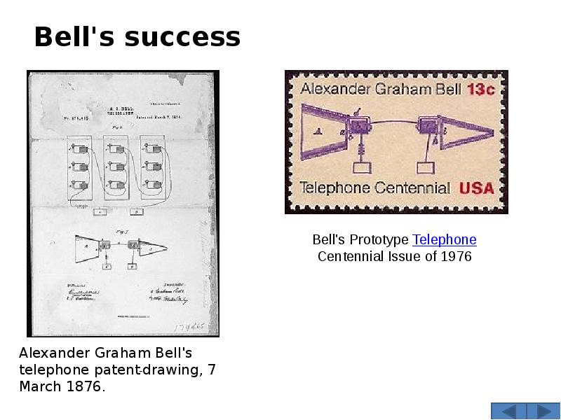
Bell's success
Описание слайда:
Bell's success

Слайд 31


The first long distance telephone call was made on 10 August 1876 by Bell from the family homestead in Brantford, Ontario, to his assistant located in Paris, Ontario, some 10 miles (16 km) distant.
A finished instrument was then made, having a transmitter formed of a double electromagnet, in front of which a membrane, stretched on a ring, carried an oblong piece of soft iron cemented to its middle. A mouthpiece before the diaphragm directed the sounds upon it, and as it vibrated with them, the soft iron “armature” induced corresponding currents in the coils of the electromagnet. These currents after traversing the line were passed through the receiver, which consisted of a tubular electromagnet, having one end partially closed by a thin circular disc of soft iron fixed at one point to the end of the tube. This receiver bore a resemblance to a cylindrical metal box with thick sides, having a thin iron lid fastened to its mouth by a single screw. When the undulatory current passed through the coil of this magnet, the disc, or armature-lid, was put into vibration and sounds were emitted from it.
Описание слайда:
The first long distance telephone call was made on 10 August 1876 by Bell from the family homestead in Brantford, Ontario, to his assistant located in Paris, Ontario, some 10 miles (16 km) distant. The first long distance telephone call was made on 10 August 1876 by Bell from the family homestead in Brantford, Ontario, to his assistant located in Paris, Ontario, some 10 miles (16 km) distant. A finished instrument was then made, having a transmitter formed of a double electromagnet, in front of which a membrane, stretched on a ring, carried an oblong piece of soft iron cemented to its middle. A mouthpiece before the diaphragm directed the sounds upon it, and as it vibrated with them, the soft iron “armature” induced corresponding currents in the coils of the electromagnet. These currents after traversing the line were passed through the receiver, which consisted of a tubular electromagnet, having one end partially closed by a thin circular disc of soft iron fixed at one point to the end of the tube. This receiver bore a resemblance to a cylindrical metal box with thick sides, having a thin iron lid fastened to its mouth by a single screw. When the undulatory current passed through the coil of this magnet, the disc, or armature-lid, was put into vibration and sounds were emitted from it.

Слайд 32


This primitive telephone was rapidly improved, the double electromagnet being replaced by a single bar magnet having a small coil or bobbin of fine wire surrounding one pole, in front of which a thin disc of ferrotype was fixed in a circular mouthpiece, and served as a combined membrane and armature. On speaking into the mouthpiece, the iron diaphragm vibrated with the voice in the magnetic field of the pole, and thereby caused undulatory currents in the coil, which, after traveling through the wire to the distant receiver, were received in an identical apparatus. This form was patented January 30, 1877. The sounds were weak and could only be heard when the ear was close to the earphone/mouthpiece, but they were distinct.
Описание слайда:
This primitive telephone was rapidly improved, the double electromagnet being replaced by a single bar magnet having a small coil or bobbin of fine wire surrounding one pole, in front of which a thin disc of ferrotype was fixed in a circular mouthpiece, and served as a combined membrane and armature. On speaking into the mouthpiece, the iron diaphragm vibrated with the voice in the magnetic field of the pole, and thereby caused undulatory currents in the coil, which, after traveling through the wire to the distant receiver, were received in an identical apparatus. This form was patented January 30, 1877. The sounds were weak and could only be heard when the ear was close to the earphone/mouthpiece, but they were distinct. This primitive telephone was rapidly improved, the double electromagnet being replaced by a single bar magnet having a small coil or bobbin of fine wire surrounding one pole, in front of which a thin disc of ferrotype was fixed in a circular mouthpiece, and served as a combined membrane and armature. On speaking into the mouthpiece, the iron diaphragm vibrated with the voice in the magnetic field of the pole, and thereby caused undulatory currents in the coil, which, after traveling through the wire to the distant receiver, were received in an identical apparatus. This form was patented January 30, 1877. The sounds were weak and could only be heard when the ear was close to the earphone/mouthpiece, but they were distinct.

Слайд 33


Variable resistance transmitters
Water microphone - Elisha Gray
Elisha Gray recognized the lack of fidelity of the make-break transmitter of Reis and Bourseul and reasoned by analogy with the lover's telegraph, that if the current could be made to more closely model the movements of the diaphragm, rather than simply opening and closing the circuit, greater fidelity might be achieved. Gray filed a patent caveat with the US patent office on February 14, 1876 for a liquid microphone. The device used a metal needle or rod that was placed — just barely — into a liquid conductor, such as a water/acid mixture. In response to the diaphragm's vibrations, the needle dipped more or less into the liquid, varying the electrical resistance and thus the current passing through the device and on to the receiver. Gray did not convert his caveat into a patent until after the caveat had expired and hence left the field open to Bell. When Gray applied for a patent for the variable resistance telephone transmitter, the Patent Office determined "while Gray was undoubtedly the first to conceive of and disclose the [variable resistance] invention, as in his caveat of 14 February 1876.
Описание слайда:
Variable resistance transmitters Water microphone - Elisha Gray Elisha Gray recognized the lack of fidelity of the make-break transmitter of Reis and Bourseul and reasoned by analogy with the lover's telegraph, that if the current could be made to more closely model the movements of the diaphragm, rather than simply opening and closing the circuit, greater fidelity might be achieved. Gray filed a patent caveat with the US patent office on February 14, 1876 for a liquid microphone. The device used a metal needle or rod that was placed — just barely — into a liquid conductor, such as a water/acid mixture. In response to the diaphragm's vibrations, the needle dipped more or less into the liquid, varying the electrical resistance and thus the current passing through the device and on to the receiver. Gray did not convert his caveat into a patent until after the caveat had expired and hence left the field open to Bell. When Gray applied for a patent for the variable resistance telephone transmitter, the Patent Office determined "while Gray was undoubtedly the first to conceive of and disclose the [variable resistance] invention, as in his caveat of 14 February 1876.

Слайд 34


Carbon microphone - Thomas Edison
Thomas Alva Edison took the next step in improving the telephone with his invention in 1878 of the carbon grain transmitter that provided a strong voice signal on the transmitting circuit that made long-distance calls practical. Edison discovered that carbon grains, squeezed between two metal plates, had a variable electrical resistance that was related to the pressure. Thus, the grains could vary their resistance as the plates moved in response to sound waves, and reproduce sound with good fidelity, without the weak signals associated with electro-magnetic transmitters.
The carbon microphone was further improved by Emile Berliner, Francis Blake, David E. Hughes, Henry Hunnings, and Anthony White. The carbon transmitter remained standard in telephony until the 1980s, and is still being produced.
Описание слайда:
Carbon microphone - Thomas Edison Carbon microphone - Thomas Edison Thomas Alva Edison took the next step in improving the telephone with his invention in 1878 of the carbon grain transmitter that provided a strong voice signal on the transmitting circuit that made long-distance calls practical. Edison discovered that carbon grains, squeezed between two metal plates, had a variable electrical resistance that was related to the pressure. Thus, the grains could vary their resistance as the plates moved in response to sound waves, and reproduce sound with good fidelity, without the weak signals associated with electro-magnetic transmitters. The carbon microphone was further improved by Emile Berliner, Francis Blake, David E. Hughes, Henry Hunnings, and Anthony White. The carbon transmitter remained standard in telephony until the 1980s, and is still being produced.

Слайд 35


Invention of radio

Physics of wireless signalling
Several different electrical, magnetic, or electromagnetic physical phenomena can be used to transmit signals over a distance without intervening wires. The various methods for wireless signal transmissions include:
Electrical Conduction through the ground, or through water. 
Magnetic induction 
Capacitive coupling 
Electromagnetic waves
Описание слайда:
Invention of radio Physics of wireless signalling Several different electrical, magnetic, or electromagnetic physical phenomena can be used to transmit signals over a distance without intervening wires. The various methods for wireless signal transmissions include: Electrical Conduction through the ground, or through water. Magnetic induction Capacitive coupling Electromagnetic waves

Слайд 36


All these physical phenomena, as well as more speculative concepts such as conduction through air, have been tested for purposes of communication. Early researchers may not have understood or disclosed which physical effects were responsible for transmitting signals. Early experiments used the existing theories of the movement of charged particles through an electrical conductor. There was no theory of electromagnetic wave propagation to guide experiments before Maxwell's treatise and its verification by Hertz and others.
Capacitive and inductive coupling systems today are used only for short-range special purpose systems. The physical phenomenon used generally today for long-distance wireless communications involves the use of modulation of electromagnetic
Описание слайда:
All these physical phenomena, as well as more speculative concepts such as conduction through air, have been tested for purposes of communication. Early researchers may not have understood or disclosed which physical effects were responsible for transmitting signals. Early experiments used the existing theories of the movement of charged particles through an electrical conductor. There was no theory of electromagnetic wave propagation to guide experiments before Maxwell's treatise and its verification by Hertz and others. All these physical phenomena, as well as more speculative concepts such as conduction through air, have been tested for purposes of communication. Early researchers may not have understood or disclosed which physical effects were responsible for transmitting signals. Early experiments used the existing theories of the movement of charged particles through an electrical conductor. There was no theory of electromagnetic wave propagation to guide experiments before Maxwell's treatise and its verification by Hertz and others. Capacitive and inductive coupling systems today are used only for short-range special purpose systems. The physical phenomenon used generally today for long-distance wireless communications involves the use of modulation of electromagnetic

Слайд 37


Radio antennas radiate electromagnetic waves that can reach the receiver either by ground-wave propagation, by refraction from the ionosphere, known as sky-wave propagation, and occasionally by refraction in lower layers of the atmosphere (tropospheric ducting). The ground-wave component is the portion of the radiated electromagnetic wave that propagates close to the Earth's surface. It has both direct-wave and ground-reflected components. The direct-wave is limited only by the distance from the transmitter to the horizon plus a distance added by diffraction around the curvature of the earth. The ground-reflected portion of the radiated wave reaches the receiving antenna after being reflected from the Earth's surface. A portion of the ground-wave energy radiated by the antenna may also be guided by the Earth's surface as a ground-hugging surface wave.
Описание слайда:
Radio antennas radiate electromagnetic waves that can reach the receiver either by ground-wave propagation, by refraction from the ionosphere, known as sky-wave propagation, and occasionally by refraction in lower layers of the atmosphere (tropospheric ducting). The ground-wave component is the portion of the radiated electromagnetic wave that propagates close to the Earth's surface. It has both direct-wave and ground-reflected components. The direct-wave is limited only by the distance from the transmitter to the horizon plus a distance added by diffraction around the curvature of the earth. The ground-reflected portion of the radiated wave reaches the receiving antenna after being reflected from the Earth's surface. A portion of the ground-wave energy radiated by the antenna may also be guided by the Earth's surface as a ground-hugging surface wave. Radio antennas radiate electromagnetic waves that can reach the receiver either by ground-wave propagation, by refraction from the ionosphere, known as sky-wave propagation, and occasionally by refraction in lower layers of the atmosphere (tropospheric ducting). The ground-wave component is the portion of the radiated electromagnetic wave that propagates close to the Earth's surface. It has both direct-wave and ground-reflected components. The direct-wave is limited only by the distance from the transmitter to the horizon plus a distance added by diffraction around the curvature of the earth. The ground-reflected portion of the radiated wave reaches the receiving antenna after being reflected from the Earth's surface. A portion of the ground-wave energy radiated by the antenna may also be guided by the Earth's surface as a ground-hugging surface wave.

Слайд 38


Hertz

Heinrich Rudolf Hertz was the experimental physicist who confirmed Maxwell's work in the laboratory.[6] From 1886 to 1888 inclusive, in his UHF experiments, he transmitted and received radio waves over short distances and showed that the properties of radio waves were consistent with Maxwell’s electromagnetic theory. He demonstrated that radio radiation had all the properties of waves (now called electromagnetic radiation), and discovered that the electromagnetic equations could be reformulated into a partial differential equation called the wave equation.
Hertz used the damped oscillating currents in a dipole antenna, triggered by a high-voltage electrical capacitive spark discharge, as his source of radio waves. His detector in some experiments was another dipole antenna connected to a narrow spark gap. A small spark in this gap signified detection of the radio waves. When he added cylindrical reflectors behind his dipole antennas, Hertz could detect radio waves about 20 metres from the transmitter in his laboratory. He did not try to transmit further because he wanted to prove electromagnetic theory, not to develop wireless communications.
Описание слайда:
Hertz Heinrich Rudolf Hertz was the experimental physicist who confirmed Maxwell's work in the laboratory.[6] From 1886 to 1888 inclusive, in his UHF experiments, he transmitted and received radio waves over short distances and showed that the properties of radio waves were consistent with Maxwell’s electromagnetic theory. He demonstrated that radio radiation had all the properties of waves (now called electromagnetic radiation), and discovered that the electromagnetic equations could be reformulated into a partial differential equation called the wave equation. Hertz used the damped oscillating currents in a dipole antenna, triggered by a high-voltage electrical capacitive spark discharge, as his source of radio waves. His detector in some experiments was another dipole antenna connected to a narrow spark gap. A small spark in this gap signified detection of the radio waves. When he added cylindrical reflectors behind his dipole antennas, Hertz could detect radio waves about 20 metres from the transmitter in his laboratory. He did not try to transmit further because he wanted to prove electromagnetic theory, not to develop wireless communications.

Слайд 39


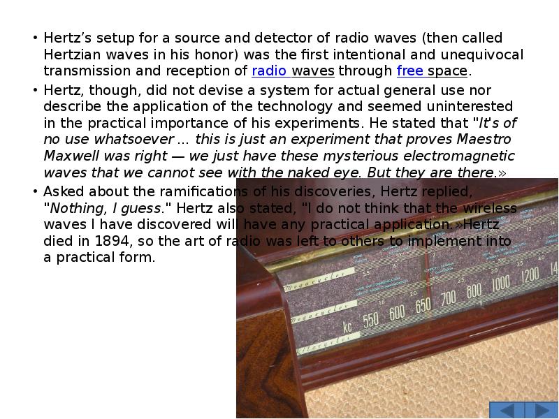
Hertz’s setup for a source and detector of radio waves (then called Hertzian waves in his honor) was the first intentional and unequivocal transmission and reception of radio waves through free space.
Hertz, though, did not devise a system for actual general use nor describe the application of the technology and seemed uninterested in the practical importance of his experiments. He stated that "It's of no use whatsoever ... this is just an experiment that proves Maestro Maxwell was right — we just have these mysterious electromagnetic waves that we cannot see with the naked eye. But they are there.»
Asked about the ramifications of his discoveries, Hertz replied, "Nothing, I guess." Hertz also stated, "I do not think that the wireless waves I have discovered will have any practical application.»Hertz died in 1894, so the art of radio was left to others to implement into a practical form.
Описание слайда:
Hertz’s setup for a source and detector of radio waves (then called Hertzian waves in his honor) was the first intentional and unequivocal transmission and reception of radio waves through free space. Hertz’s setup for a source and detector of radio waves (then called Hertzian waves in his honor) was the first intentional and unequivocal transmission and reception of radio waves through free space. Hertz, though, did not devise a system for actual general use nor describe the application of the technology and seemed uninterested in the practical importance of his experiments. He stated that "It's of no use whatsoever ... this is just an experiment that proves Maestro Maxwell was right — we just have these mysterious electromagnetic waves that we cannot see with the naked eye. But they are there.» Asked about the ramifications of his discoveries, Hertz replied, "Nothing, I guess." Hertz also stated, "I do not think that the wireless waves I have discovered will have any practical application.»Hertz died in 1894, so the art of radio was left to others to implement into a practical form.

Слайд 40


Tesla

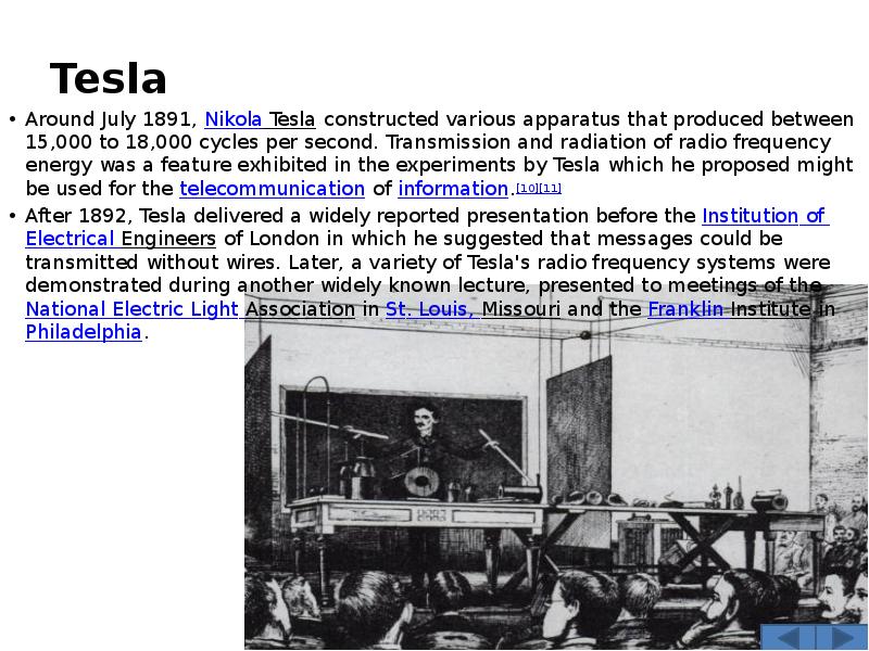
Around July 1891, Nikola Tesla constructed various apparatus that produced between 15,000 to 18,000 cycles per second. Transmission and radiation of radio frequency energy was a feature exhibited in the experiments by Tesla which he proposed might be used for the telecommunication of information.[10][11]
After 1892, Tesla delivered a widely reported presentation before the Institution of Electrical Engineers of London in which he suggested that messages could be transmitted without wires. Later, a variety of Tesla's radio frequency systems were demonstrated during another widely known lecture, presented to meetings of the National Electric Light Association in St. Louis, Missouri and the Franklin Institute in Philadelphia.
Описание слайда:
Tesla Around July 1891, Nikola Tesla constructed various apparatus that produced between 15,000 to 18,000 cycles per second. Transmission and radiation of radio frequency energy was a feature exhibited in the experiments by Tesla which he proposed might be used for the telecommunication of information.[10][11] After 1892, Tesla delivered a widely reported presentation before the Institution of Electrical Engineers of London in which he suggested that messages could be transmitted without wires. Later, a variety of Tesla's radio frequency systems were demonstrated during another widely known lecture, presented to meetings of the National Electric Light Association in St. Louis, Missouri and the Franklin Institute in Philadelphia.

Слайд 41


Bose
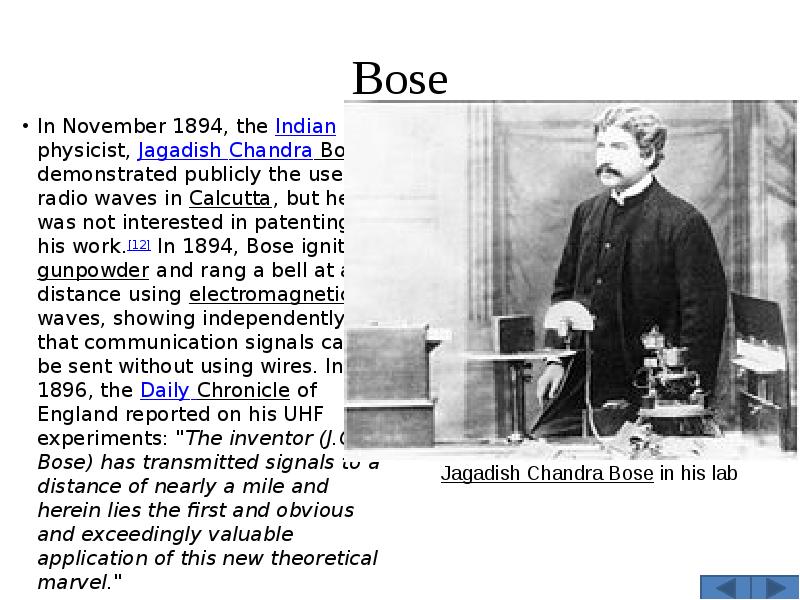
In November 1894, the Indian physicist, Jagadish Chandra Bose, demonstrated publicly the use of radio waves in Calcutta, but he was not interested in patenting his work.[12] In 1894, Bose ignited gunpowder and rang a bell at a distance using electromagnetic waves, showing independently that communication signals can be sent without using wires. In 1896, the Daily Chronicle of England reported on his UHF experiments: "The inventor (J.C. Bose) has transmitted signals to a distance of nearly a mile and herein lies the first and obvious and exceedingly valuable application of this new theoretical marvel."
Описание слайда:
Bose In November 1894, the Indian physicist, Jagadish Chandra Bose, demonstrated publicly the use of radio waves in Calcutta, but he was not interested in patenting his work.[12] In 1894, Bose ignited gunpowder and rang a bell at a distance using electromagnetic waves, showing independently that communication signals can be sent without using wires. In 1896, the Daily Chronicle of England reported on his UHF experiments: "The inventor (J.C. Bose) has transmitted signals to a distance of nearly a mile and herein lies the first and obvious and exceedingly valuable application of this new theoretical marvel."

Слайд 42


Braun

In 1897 Ferdinand Braun joined the line of wireless pioneers. His major contributions were the introduction of a closed tuned circuit in the generating part of the transmitter, and its separation from the radiating part (the antenna) by means of inductive coupling, and later on the usage of crystals for receiving purposes.
All pioneers working on wireless devices came to a limit of distance they could cover. Connecting the antenna directly to the spark gap produced only a heavily damped pulse train. There were only a few cycles before oscillations ceased. Braun's circuit afforded a much longer sustained oscillation because the energy encountered less losses swinging between coil and Leyden Jars. And by means of inductive antenna coupling the radiator was better matched to the generator. The resultant stronger and less bandwidth consuming signals bridged a much longer distance.
Описание слайда:
Braun In 1897 Ferdinand Braun joined the line of wireless pioneers. His major contributions were the introduction of a closed tuned circuit in the generating part of the transmitter, and its separation from the radiating part (the antenna) by means of inductive coupling, and later on the usage of crystals for receiving purposes. All pioneers working on wireless devices came to a limit of distance they could cover. Connecting the antenna directly to the spark gap produced only a heavily damped pulse train. There were only a few cycles before oscillations ceased. Braun's circuit afforded a much longer sustained oscillation because the energy encountered less losses swinging between coil and Leyden Jars. And by means of inductive antenna coupling the radiator was better matched to the generator. The resultant stronger and less bandwidth consuming signals bridged a much longer distance.

Слайд 43


The Nobel Prize awarded to Braun in 1909 depicts this design.
Braun experimented at first at the University of Strassbourg. Not before long he bridged a distance of 42 km to the city of Mutzing. In spring 1899 Braun, accompanied by his colleagues Cantor and Zenneck, went to Cuxhaven to continue their experiments at the North Sea. On 24th September 1900 radio telegraphy signals were exchanged regularly with the island of Heligoland over a distance of 62 km. Lightvessels in the river Elbe and a coast station at Cuxhaven commenced a regular radio telegraph service.
Описание слайда:
The Nobel Prize awarded to Braun in 1909 depicts this design. The Nobel Prize awarded to Braun in 1909 depicts this design. Braun experimented at first at the University of Strassbourg. Not before long he bridged a distance of 42 km to the city of Mutzing. In spring 1899 Braun, accompanied by his colleagues Cantor and Zenneck, went to Cuxhaven to continue their experiments at the North Sea. On 24th September 1900 radio telegraphy signals were exchanged regularly with the island of Heligoland over a distance of 62 km. Lightvessels in the river Elbe and a coast station at Cuxhaven commenced a regular radio telegraph service.

Слайд 44


Early commercial exploitation
Описание слайда:
Early commercial exploitation

Слайд 45


Popov
Beginning in the early 1890s, Alexander Stepanovich Popov conducted experiments along the lines of Hertz's research. In 1894-95 he built his first radio receiver, an improved version of coherer-based design by Oliver Lodge. He presented it to the Russian Physical and Chemical Society on May 7, 1895 — the day has been celebrated in the Russian Federation as "Radio Day". The paper on his findings was published the same year (December 15, 1895). Popov had recorded, at the end of 1895, that he was hoping for distant signaling with radio waves.
Описание слайда:
Popov Beginning in the early 1890s, Alexander Stepanovich Popov conducted experiments along the lines of Hertz's research. In 1894-95 he built his first radio receiver, an improved version of coherer-based design by Oliver Lodge. He presented it to the Russian Physical and Chemical Society on May 7, 1895 — the day has been celebrated in the Russian Federation as "Radio Day". The paper on his findings was published the same year (December 15, 1895). Popov had recorded, at the end of 1895, that he was hoping for distant signaling with radio waves.

Слайд 46


In the years that followed, Popov worked on his design. His receiver proved to be able to sense lightning strikes at distances of up to 30 km, thus functioning as a lightning detector. In late 1895, Popov built a version of the receiver that was capable of automatically recording lightning strikes on paper rolls. Popov's system was eventually extended to function as a wireless telegraph, with a Morse key attached to the transmitter. There's some dispute regarding the first public test of this design. It is frequently stated that Popov used his radio to send a Morse code message over a distance of 250 m in March 1896 (three months before Marconi's patent was filed). However, contemporary confirmations of this transmission are lacking. It is more likely that said experiment took place in December 1897.
In 1900 a radio station was established under Popov's instructions on Hogland island (Suursaari) to provide two-way communication by wireless telegraphy between the Russian naval base and the crew of the battleship General-Admiral Apraksin. By February 5 messages were being received reliably. The wireless messages were relayed to Hogland Island by a station some 25 miles away at Kymi (nowadays Kotka) on the Finnish coast.
Описание слайда:
In the years that followed, Popov worked on his design. His receiver proved to be able to sense lightning strikes at distances of up to 30 km, thus functioning as a lightning detector. In late 1895, Popov built a version of the receiver that was capable of automatically recording lightning strikes on paper rolls. Popov's system was eventually extended to function as a wireless telegraph, with a Morse key attached to the transmitter. There's some dispute regarding the first public test of this design. It is frequently stated that Popov used his radio to send a Morse code message over a distance of 250 m in March 1896 (three months before Marconi's patent was filed). However, contemporary confirmations of this transmission are lacking. It is more likely that said experiment took place in December 1897. In the years that followed, Popov worked on his design. His receiver proved to be able to sense lightning strikes at distances of up to 30 km, thus functioning as a lightning detector. In late 1895, Popov built a version of the receiver that was capable of automatically recording lightning strikes on paper rolls. Popov's system was eventually extended to function as a wireless telegraph, with a Morse key attached to the transmitter. There's some dispute regarding the first public test of this design. It is frequently stated that Popov used his radio to send a Morse code message over a distance of 250 m in March 1896 (three months before Marconi's patent was filed). However, contemporary confirmations of this transmission are lacking. It is more likely that said experiment took place in December 1897. In 1900 a radio station was established under Popov's instructions on Hogland island (Suursaari) to provide two-way communication by wireless telegraphy between the Russian naval base and the crew of the battleship General-Admiral Apraksin. By February 5 messages were being received reliably. The wireless messages were relayed to Hogland Island by a station some 25 miles away at Kymi (nowadays Kotka) on the Finnish coast.

Слайд 47


Marconi

Marconi's early apparatus was a development of Hertz’s laboratory apparatus into a system designed for communications purposes. At first Marconi used a transmitter to ring a bell in a receiver in his attic laboratory. He then moved his experiments out-of-doors on the family estate near Bologna, Italy, to communicate further. He replaced Hertz’s vertical dipole with a vertical wire topped by a metal sheet, with an opposing terminal connected to the ground. On the receiver side, Marconi replaced the spark gap with a metal powder coherer, a detector developed by
Описание слайда:
Marconi Marconi's early apparatus was a development of Hertz’s laboratory apparatus into a system designed for communications purposes. At first Marconi used a transmitter to ring a bell in a receiver in his attic laboratory. He then moved his experiments out-of-doors on the family estate near Bologna, Italy, to communicate further. He replaced Hertz’s vertical dipole with a vertical wire topped by a metal sheet, with an opposing terminal connected to the ground. On the receiver side, Marconi replaced the spark gap with a metal powder coherer, a detector developed by

Слайд 48


By 1896, Marconi introduced to the public a device in London, asserting it was his invention. Despite Marconi's statements to the contrary, though, the apparatus resembles Tesla's descriptions in the widely translated articles.[19] Marconi's later practical four-tuned system was pre-dated by N. Tesla, Oliver Lodge, and J. S. Stone.[20] He filed a patent on his system with the British Patent Office on June 2, 1896.
Marconi's reputation is largely based on these accomplishments in radio communications and commercializing a practical system. His demonstrations of the use of radio for wireless communications, equipping ships with life saving wireless communications, establishing the first transatlantic radio service, and building the first stations for the British short wave service, have marked his place in history.
Описание слайда:
By 1896, Marconi introduced to the public a device in London, asserting it was his invention. Despite Marconi's statements to the contrary, though, the apparatus resembles Tesla's descriptions in the widely translated articles.[19] Marconi's later practical four-tuned system was pre-dated by N. Tesla, Oliver Lodge, and J. S. Stone.[20] He filed a patent on his system with the British Patent Office on June 2, 1896. By 1896, Marconi introduced to the public a device in London, asserting it was his invention. Despite Marconi's statements to the contrary, though, the apparatus resembles Tesla's descriptions in the widely translated articles.[19] Marconi's later practical four-tuned system was pre-dated by N. Tesla, Oliver Lodge, and J. S. Stone.[20] He filed a patent on his system with the British Patent Office on June 2, 1896. Marconi's reputation is largely based on these accomplishments in radio communications and commercializing a practical system. His demonstrations of the use of radio for wireless communications, equipping ships with life saving wireless communications, establishing the first transatlantic radio service, and building the first stations for the British short wave service, have marked his place in history.

Слайд 49


Transatlantic transmissions
In 1901, Marconi claimed to have received daytime transatlantic radio frequency signals at a wavelength of 366 metres (820 kHz). There are various science historians, such as Belrose and Bradford, who have cast doubt that the Atlantic was bridged in 1901, but other science historians have taken the position that this was the first transatlantic radio transmission. The Poldhu to Newfoundland transmission claim has been criticized. Critics have claimed that it is more likely that Marconi received stray atmospheric noise from atmospheric electricity in this experiment.The transmitting station in Poldhu, Cornwall used a spark-gap transmitter that could produce a signal in the medium frequency range and with high power levels.The message received was the Morse letter 'S' - three dots. Bradford has recently contested this, however,
Описание слайда:
Transatlantic transmissions In 1901, Marconi claimed to have received daytime transatlantic radio frequency signals at a wavelength of 366 metres (820 kHz). There are various science historians, such as Belrose and Bradford, who have cast doubt that the Atlantic was bridged in 1901, but other science historians have taken the position that this was the first transatlantic radio transmission. The Poldhu to Newfoundland transmission claim has been criticized. Critics have claimed that it is more likely that Marconi received stray atmospheric noise from atmospheric electricity in this experiment.The transmitting station in Poldhu, Cornwall used a spark-gap transmitter that could produce a signal in the medium frequency range and with high power levels.The message received was the Morse letter 'S' - three dots. Bradford has recently contested this, however,

Слайд 50


based on theoretical work as well as a reenactment of the experiment; it is possible that what was heard was only random atmospheric noise, which was mistaken for a signal, or that Marconi may have heard a shortwave harmonic of the signal.
In 1902, Marconi transmitted from his station in Glace Bay, Nova Scotia, Canada across the Atlantic, and on 18 January 1903 a Marconi station built in Wellfleet, Massachusetts in 1901 sent a message of greetings from Theodore Roosevelt, the President of the United States, to King Edward VII of the United Kingdom, marking the first transatlantic radio transmission originating in the United States.
Marconi would later found the Marconi Company and would jointly receive the 1909 Nobel Prize in Physics with Karl Ferdinand Braun for contribution to the existing radio sciences.
Описание слайда:
based on theoretical work as well as a reenactment of the experiment; it is possible that what was heard was only random atmospheric noise, which was mistaken for a signal, or that Marconi may have heard a shortwave harmonic of the signal. based on theoretical work as well as a reenactment of the experiment; it is possible that what was heard was only random atmospheric noise, which was mistaken for a signal, or that Marconi may have heard a shortwave harmonic of the signal. In 1902, Marconi transmitted from his station in Glace Bay, Nova Scotia, Canada across the Atlantic, and on 18 January 1903 a Marconi station built in Wellfleet, Massachusetts in 1901 sent a message of greetings from Theodore Roosevelt, the President of the United States, to King Edward VII of the United Kingdom, marking the first transatlantic radio transmission originating in the United States. Marconi would later found the Marconi Company and would jointly receive the 1909 Nobel Prize in Physics with Karl Ferdinand Braun for contribution to the existing radio sciences.

Слайд 51


Fessenden

In late 1886, Fessenden began working directly for Thomas Edison at the inventor's new laboratory in West Orange, New Jersey. Fessenden quickly made major advances, especially in receiver design, as he worked to develop audio reception of signals. By 1900, Fessenden was working for the United States Weather Bureau where he evolved the heterodyne principle where two signals combined produce a third audible tone. While there, Fessenden, experimenting with a high-frequency spark transmitter, successfully transmitted speech on December 23, 1900 over a distance of about 1.6 kilometers (one mile), the first audio radio transmission.
Описание слайда:
Fessenden In late 1886, Fessenden began working directly for Thomas Edison at the inventor's new laboratory in West Orange, New Jersey. Fessenden quickly made major advances, especially in receiver design, as he worked to develop audio reception of signals. By 1900, Fessenden was working for the United States Weather Bureau where he evolved the heterodyne principle where two signals combined produce a third audible tone. While there, Fessenden, experimenting with a high-frequency spark transmitter, successfully transmitted speech on December 23, 1900 over a distance of about 1.6 kilometers (one mile), the first audio radio transmission.


Теги Invention
Похожие презентации
Mypresentation.ru
Загрузить презентацию